Solar Architecture · A Field Manual for the Future City
We built the sun machine. Then we forgot.
Over a century ago, engineers ran engines, made ice, and pumped rivers using nothing but
focused sunlight. The technology worked. We abandoned it for cheap oil. This is the case for switching it back on —
and building it into the grandest structures we ever made.
↓ The lost century of solar power
The Idea
A magnifying glass, scaled up to power a city.
A child's magnifying glass bunches sunlight into a dot hot enough to burn paper. Make the lens
big enough and that dot boils water. Boiling water makes steam; steam spins a
generator; that's electricity — no fuel, no smoke, no bill. Set one in
every bay or hundreds across a district — the count follows the building and the size of the
lens. A bigger lens gathers more, but large lenses are hard to build and harder still to cool,
so the honest design is many modest spheres rather than one heroic one. Either way the structure itself becomes
the power plant.
This isn't science fiction. It's a 250-year-old idea that was demonstrated, commercialized,
and then shelved when coal and oil got cheap. The physics never stopped working. We just stopped building it.
The Evidence · 1767–Today
The lost century of the sun engine
Every entry below is documented. Where a number is a period claim and not an independent
modern measurement, it's marked — because the honest record is the one skeptics can't break.
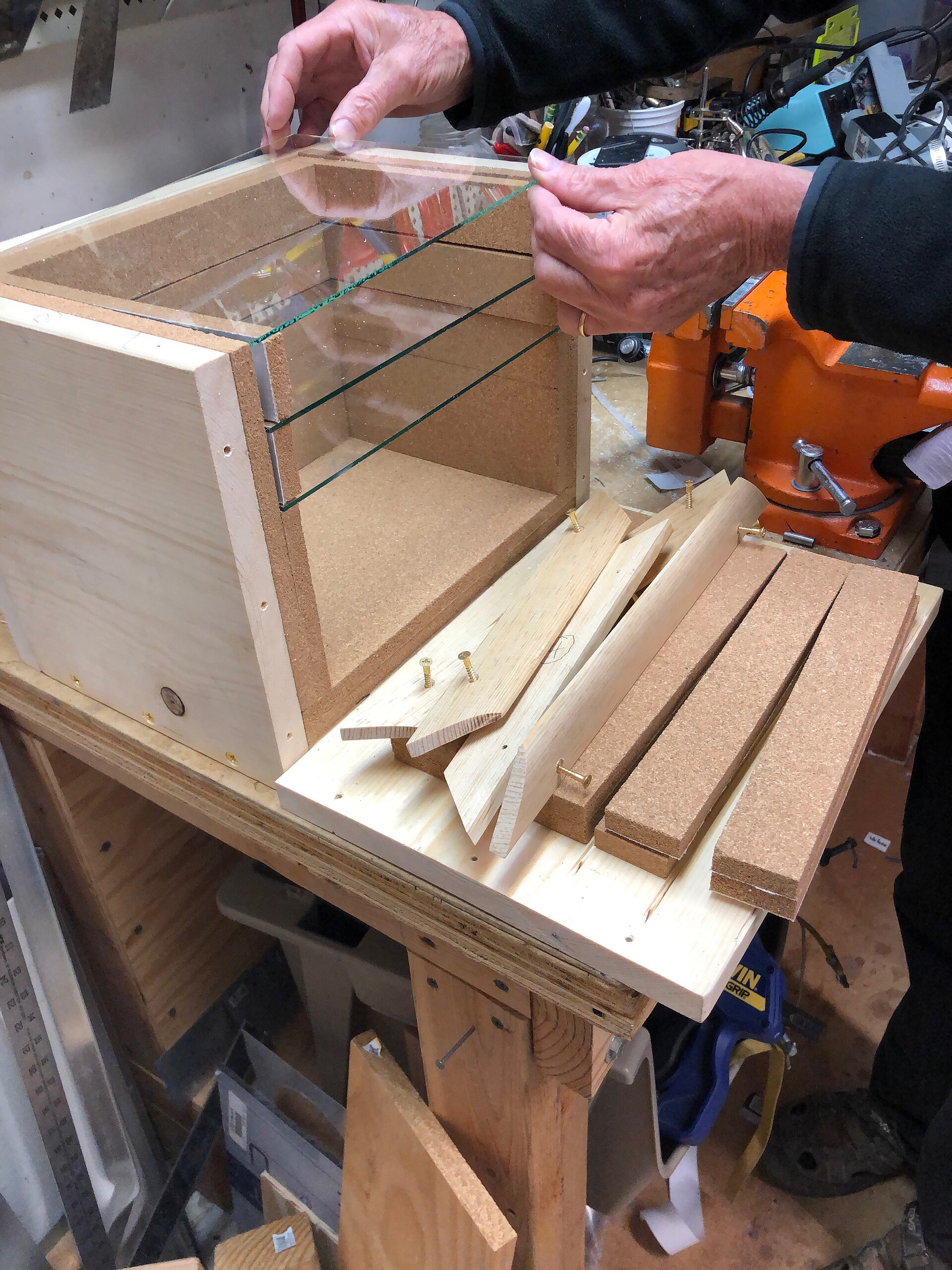
1767+ photo & detail
Saussure's hot box
Swiss scientist Horace-Bénédict de Saussure builds the first known Western solar oven — an insulated,
triple-glazed glass heat trap that reached roughly 110 °C from sunlight alone.
His "heliothermometer" was a simple wooden box with three panes of glass that let sunlight in but trapped
the heat. He carried versions up into the Alps to prove the warmth came from the sun itself, not the air.
Every greenhouse, solar collector, and "hot box" cooker since descends from this experiment.
How it worked — the first greenhouse trap
1
Glazing — sunlight passed through three stacked panes of glass on top of a cork-insulated pine box.
2
Black interior — it struck a soot-blackened inside and was absorbed as heat.
3
The trap — the panes let visible light in but blocked the outgoing heat and stifled convection, so warmth piled up.
4
Read-out — a thermometer at the bottom logged the temperature. No lens, no mirror — just trapped sun.
3 glass panes~110 °C (self-report)cork-insulated1767
The ~110 °C (230 °F) figure is de Saussure's own 18th-century reading, never re-measured on the original box. It's the direct ancestor of every greenhouse and flat-plate solar collector.
Image: heliothermometer reconstruction · Wikimedia Commons, CC BY-SA 4.0 · Source: Saussure (Wikipedia); Butti & Perlin, A Golden Thread; Paléo-Énergétique
1770s+ photo & detail
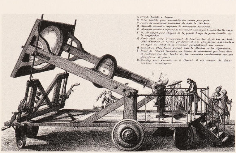
Lavoisier's burning lens
Chemist Antoine Lavoisier and colleagues run a long series of experiments (from 1772) with the great
Trudaine "burning lens" — a two-part concentrator that melted metals and even burned
diamond. Even so, it couldn't melt platinum — the practical ceiling of 18th-century solar
concentration. Platinum finally fell in 1782, to an oxygen blast, not a lens.
The apparatus rode on a big wheeled carriage so it could track the sun. Its primary "lens" was actually a
huge sealed cavity of alcohol between two curved glass shells, feeding a smaller
solid-glass lens — together bringing the sun to a spot under an inch across, hot enough to melt gold and
burn diamond before crowds in Paris. But it never even softened platinum (m.p. 1,768 °C) — the era's
ceiling — until Lavoisier cracked that in 1782 with pure oxygen, not light.
How it worked — a lens made of liquid
1
Liquid primary — a large lens-shaped cavity filled with alcohol (spirits of wine) gathered the sun.
2
Glass auxiliary — a smaller ~22 cm solid-glass lens tightened the beam further.
3
Focus — the rays met in a spot under ~2.7 cm across.
4
Result — melted metals and burned diamond to gas — but stalled at platinum.
alcohol liquid lens22 cm auxiliary<2.7 cm focusPt m.p. 1,768 °C
The popular "~89 cm burning glass" is wrong — the primary was a large alcohol-filled
liquid lens, not a glass disc. Burning the diamond helped prove it was made of carbon.
Image: "The Lavoisier Lens" · Wikimedia Commons, public domain · Source: Wisniak, "Priestley, Scheele, Lavoisier and the Burning Lenses"; Johnson Matthey Technology Review
1866+ photo & detail
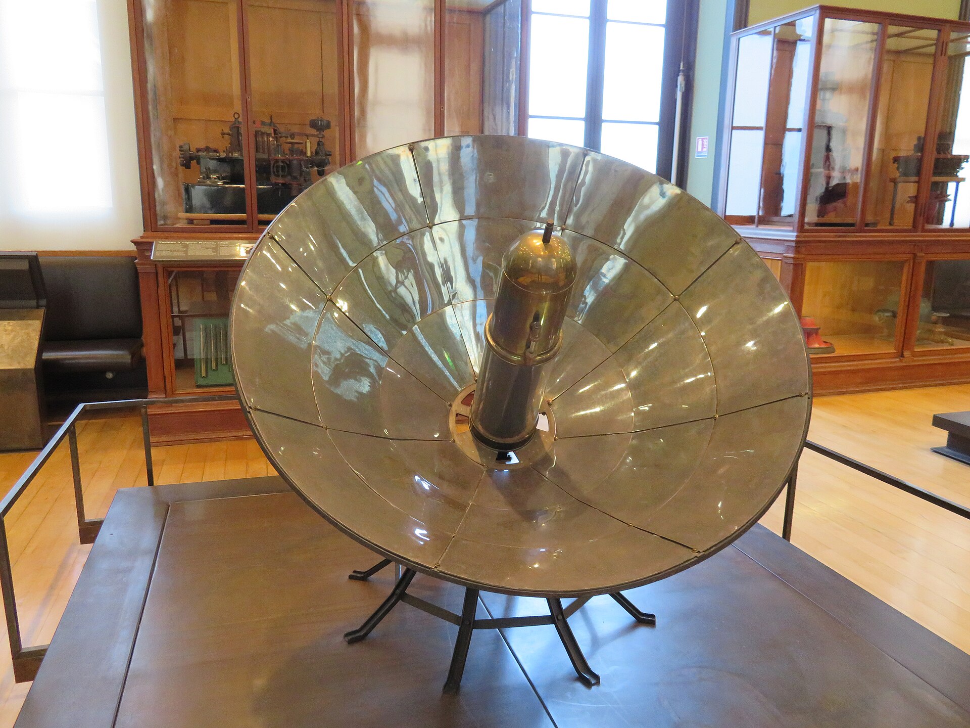
Mouchot's first solar steam engine
Frenchman Augustin Mouchot drives the world's first sun-powered steam engine — a blackened copper boiler
under a glass bell, cradled in a silvered truncated-cone reflector (not a parabola) that
concentrated the sun onto it.
His design was elegantly simple: a copper cauldron of water under a glass bell, cradled in a polished
conical reflector that focused the sun onto it. The trapped sunlight raised steam to run an engine.
Napoleon III funded the work, and Mouchot spent years building ever-larger sun-tracking reflectors.
How it worked
1
Cone reflector — a silvered truncated cone ("like a lampshade"), ~2.6 m across the mouth, made of twelve removable silver sectors, aimed at the sun.
2
Boiler — it threw the light onto a blackened double-walled copper boiler holding ~20 L of water on the axis.
3
Glass bell — a glass "cloche" around the boiler trapped the heat, greenhouse-style.
4
Engine — the steam ran a small (~½ hp) engine. Origin Tours 1865; shown to Napoleon III in 1866.
2.6 m cone12 silver sectors~20 L boilerup to 5 atm
The dimensions and Tours performance figures (20 L to 2-atm steam in ~40 min) are period specs for a device that no longer exists, never re-measured. The reflector was deliberately conical, not parabolic — the common "first parabolic trough" label is wrong.
Image: surviving Mouchot–Pifre solar collector (Musée des Arts et Métiers) · Wikimedia Commons, CC BY-SA 4.0 · Source: hotairengines.org (period description); Mouchot (Wikipedia); Paléo-Énergétique
1876+ photo & detail
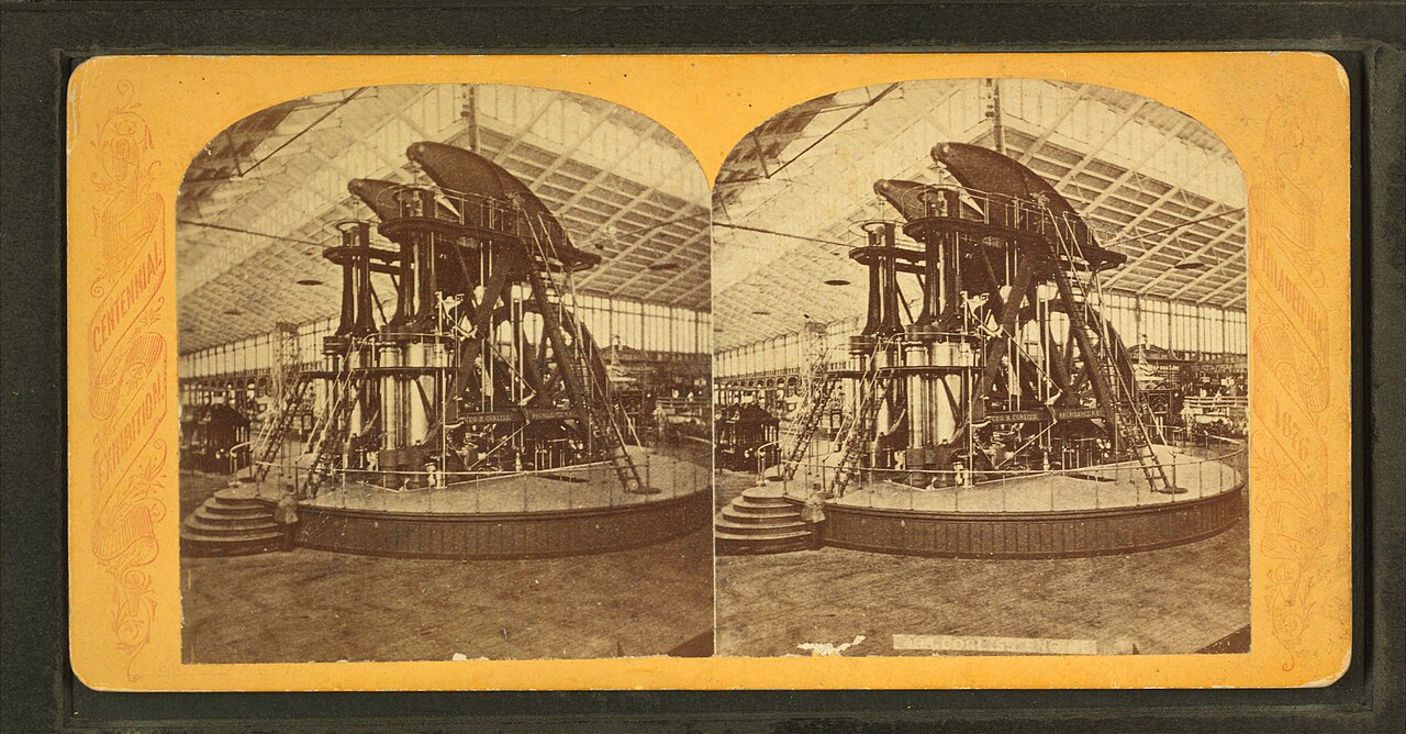
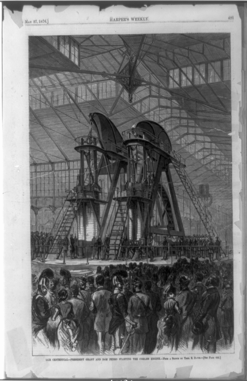
The Corliss colossus — Philadelphia Centennial
The machine solar had to out-shout: a single 1,400-horsepower Corliss steam engine,
45 ft tall, drove 13 acres of machinery through more than a mile of shafting — the beating
heart of Machinery Hall. President Grant and Emperor Dom Pedro II started it together on opening day.
World's Fair
Here's the honest detail that kills a popular myth: the 1876 Centennial gave no gold, silver,
or bronze grades at all. Every winner — Bell's telephone included — received the same
uniform bronze "Medal of Award," and the real honor was the judges' signed written report. So when you
read that Bell "won gold for electrical equipment" at Philadelphia, it never happened: there was no gold to
win. Steam, not sun, ruled this hall — and that dominance is exactly what solar was up against.
How the whole system worked
The famous engine made no steam itself. Open fires were banned inside the
timber-and-glass hall, so it was fed from a detached boiler house and simply distributed
power across the floor:
1
Boiler house — 20 coal-fired tubular boilers in a
separate building on the south side of the hall (no furnaces allowed inside), each rated ~70 nominal hp.
2
Steam main — steam piped in through a service of
pipes; one engineering account gives an 18-inch main ~320 ft long.
3
The engine — twin vertical cylinders (44-in bore,
10-ft stroke) drove a walking-beam and a 30-ft, 56-ton flywheel at ~36 rpm — about 1,400 hp at 60 psi.
4
Line shafting — the flywheel turned underground and
overhead shafts more than a mile long, belted up to each stand.
5
The floor — that single engine powered ~13 acres of
working machines throughout Machinery Hall.
1,400 hp @ 60 psi20 boilers45 ft tall30-ft flywheel · 56 t~36 rpm>1 mi shafting
Period figures vary — steam pressures from ~25 to 80 psi appear across sources, and ~2,500 hp
was claimed at 80 psi. Treat the pressures as contemporary claims, not modern measurements.
Period engraving — President Grant and Emperor Dom Pedro II start the Corliss engine on
opening day, 10 May 1876 (sketch by Theodore R. Davis). No photograph of the boiler house itself is in
the public domain; this is an engraving. · Library of Congress (LCCN 89706312), public domain
Image (top): the Corliss engine in Machinery Hall, 1876 · Robert N. Dennis stereoscopic collection · Wikimedia Commons, public domain · Sources: Gas Engine Magazine; New England Wireless & Steam Museum; Yale Energy History; Centennial Exposition (Wikipedia)
1878+ photo & detail
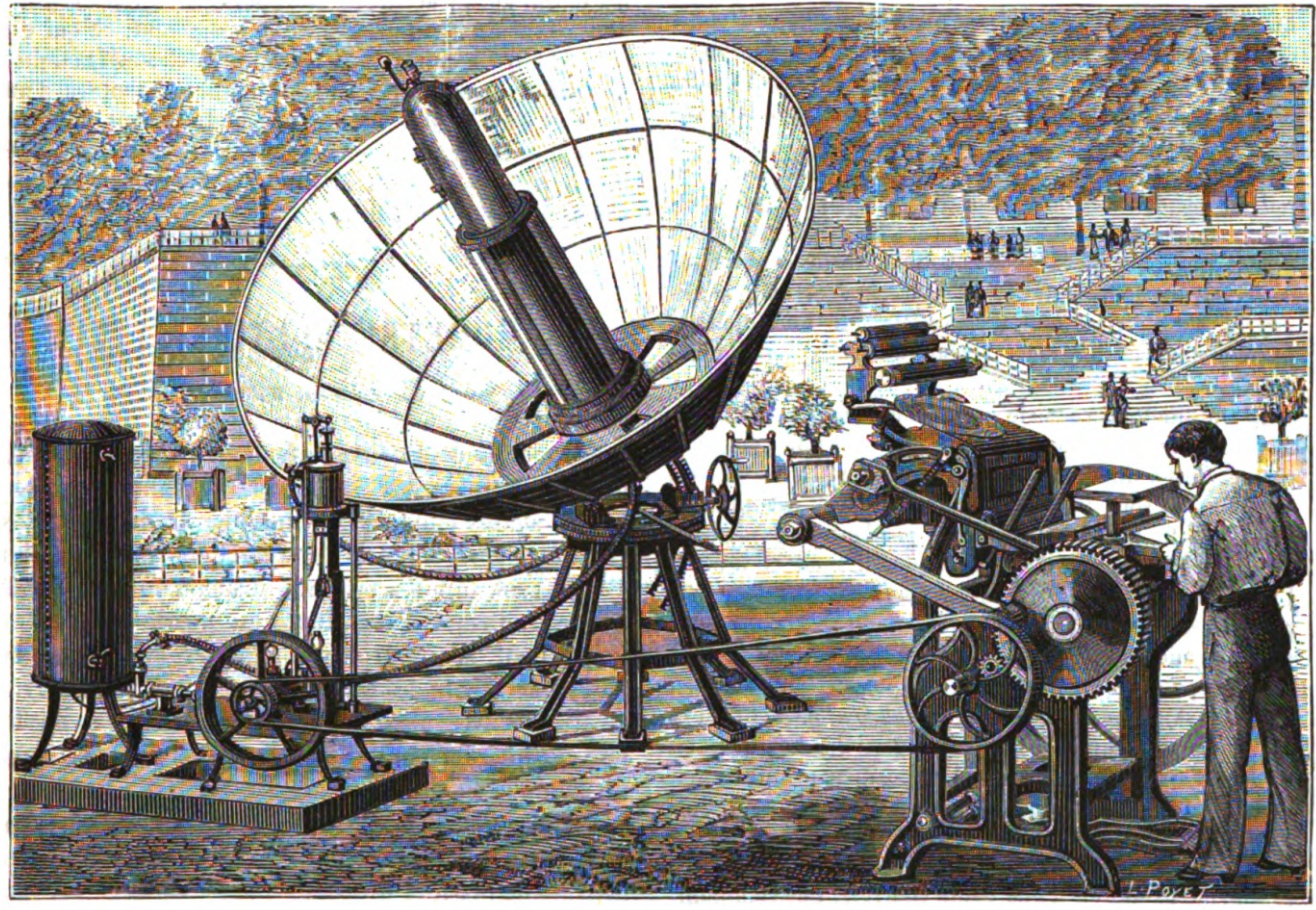
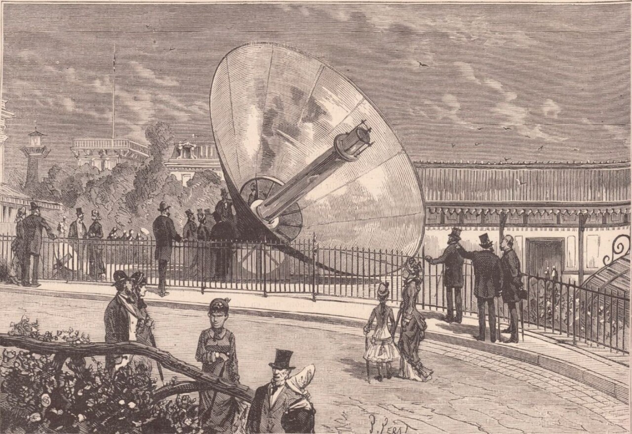
Ice from sunlight, at the Paris World's Fair
Mouchot and his assistant Abel Pifre demonstrate the solar engine at the Universal Exhibition — a mirror
over 13 ft across driving a boiler to seven atmospheres — and win a Gold
Medal in Class 54, most famously for making ice from the heat of the sun.
World's Fair
The great ~5-metre reflector stood in the open on the slopes of the Trocadéro, in the
annex of the Algerian exhibition — colonial Algiers had put up 5,000 francs to build "the largest mirror in
the world." The crowd-stopper was counter-intuitive: solar heat driving an absorption
refrigeration cycle (a Carré machine) to produce ice. It so impressed the judges
that Mouchot took the Gold Medal in Class 54 and was made a Chevalier de la Légion
d'honneur. Four years later, in 1882, Pifre used the same kind of sun-powered engine to run a printing
press in the Tuileries Gardens, printing a newspaper aptly named Le Journal du Soleil — "The Sun
Newspaper."
How it worked — steam that made ice
1
Concentrator — the giant ~5 m silvered reflector focused the sun onto a central blackened boiler.
Absorption chiller — that steam drove an Edmond Carré ammonia/water absorption refrigeration machine.
4
Ice — the absorption cycle chilled hard enough to freeze water — blocks of ice, from nothing but sunshine.
~5 m / ~20 m² mirror~7 atm steamGold Medal · Class 54Trocadéro
The actual 1878 concentrator on the Trocadéro — a Jules Férat engraving, Le Monde illustré n°1125, 19 Oct 1878. A period engraving, not a photograph. · Wikimedia Commons / Gallica-BnF, public domain
Image (top): Pifre's solar-powered printing press (based on Mouchot's concentrator) · Wikimedia Commons, CC0 · Source: Mouchot (Wikipedia); Bureau International des Expositions; worldfairs.info
1878+ detail
Adams' solar steam engine — Bombay
In Bombay, William Adams runs a solar steam plant off a battery of 16 flat-mirror
reflectors aimed at a central boiler, driving a hired 2.5-horsepower pump daily for a
fortnight — and publishes Solar Heat: A Substitute for Fuel in Tropical Countries (on Internet Archive).
Adams thought Mouchot's single giant dish was fragile and hard to aim, so he arrayed many small flat
silvered mirrors on a semicircular rack, each angled at a central boiler — the direct ancestor of every
modern "power tower" heliostat field. His 1878 book argued solar could replace coal across the tropics
for everything from cotton gins to cremation. You can read the original on Internet Archive.
How it worked — the first "power tower"
1
Mirror battery — 16 concave compound reflectors, each built of many small flat silvered glasses, ringed the boiler on a circular tramway (three-quarters of a circle, a gap left for the engine room).
2
Central boiler — from ~20 ft away they all threw sun onto one beaten-copper boiler holding 12 gallons, raising steam to ~35 lb.
3
Pump — the steam ran a hired 2.5-hp steam pump at ~30 lb — "the first steam engine ever worked in India by solar heat."
4
Tracking — workers shoved the mirrors eastward 4–5 times a day to follow the sun. Manual, not automatic — but the direct ancestor of the heliostat power-tower field.
16 reflectors12-gal boiler · ~35 lb2.5 hp pump1878 · Bombay
The widely repeated "36 mirrors / 3 hp" belongs to Adams's experiments and proposals, not this working demo (16 mirrors, a hired 2.5-hp pump). His famous "over 1,140°" focus was an extrapolated supposition — the thermometer only read past 670° for 36 glasses.
Source: W. Adams, Solar Heat: A Substitute for Fuel in Tropical Countries (1878, primary — archive.org/details/solarheatsubstit00adam); The Conversation; Ragheb, solar-thermal history
1889+ photo & detail
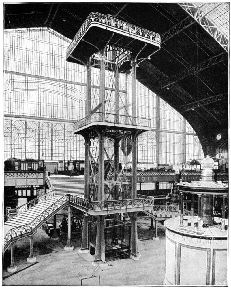
Iron cathedrals of the machine — Paris
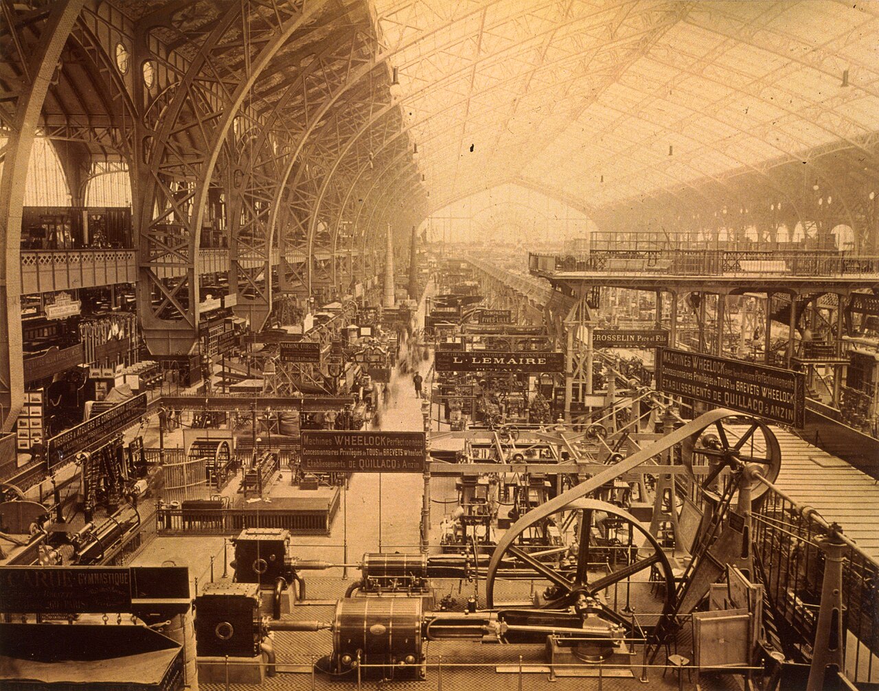
The Exposition that raised the Eiffel Tower (18,038 iron pieces) also raised the
Galerie des Machines — an iron-and-glass hall vaulting a record ~115 m in a
single span with no internal columns, the largest roofed room yet built. The age of iron architecture,
on full display. World's Fair
The Galerie borrowed three-hinged arches from bridge engineering to leap 115 metres clear — a structural
feat that made the whole hall one uninterrupted volume. Unlike Philadelphia, 1889 Paris used a fully
graded award system (903 Grand Prix, 5,153 gold medals, on down). It's the same ambition
this project chases: let the structure itself be the machine.
How it was built — a hall with no columns
1
Twenty iron arches — the roof rode on twenty giant trussed arches, a technique lifted straight from bridge engineering.
2
Three hinges each — every arch was pinned at three points: its two feet and its crown, making it "statically determinate."
3
Why hinges? — as the iron heated, cooled, or the ground settled, the arches simply rotated a little about their pins instead of cracking under bending stress.
4
The payoff — the arches sprang from foundation abutments and met overhead with nothing between: a clear span near 115 m and a completely column-free floor, the widest roofed room on Earth at the time.
~115 m clear span420 m long~45 m high20 arches
The span is cited anywhere from 111 to 117 m (115 m is the usual round figure); crown height appears as ~45 m or an oddly exact 48.3 m — treat both as period/derived. Engineer Victor Contamin, architect Ferdinand Dutert.
The finished hall — a photochrom of the column-free interior, 1889. · Library of Congress (LCCN 2001698576, LC-DIG-ppmsc-05215), no known restrictions · public domain by age
Image (top): interior of the Galerie des Machines, 1889 · Engineering journal · Wikimedia Commons, public domain · Sources: Britannica; J. Stamper (T&F); Galerie des machines (Wikipedia); Cnam/Cnum
1893+ photo & detail
Electricity takes the stage — Chicago
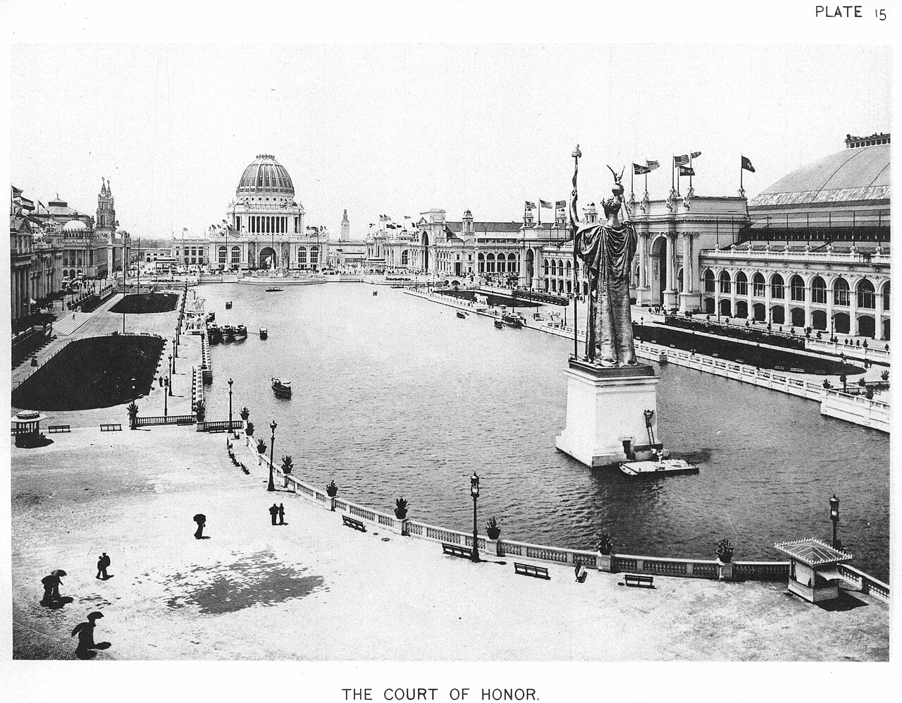
At the World's Columbian Exposition, Westinghouse won the contract to light the fair with
alternating current, underbidding Edison/GE ($399,000 vs $554,000). The "White City" blazed with
~93,000 lamps — the public debut of the power system that would electrify the century.
World's Fair
This is the turning point in the honest story: not solar, but cheap, controllable
electricity — soon fed by coal and Niagara's water — is what captured the future. (Like Philadelphia,
Chicago gave a single uniform bronze medal, no gold grades; the "gold medal to a British locomotive" tale
doesn't hold up.) The sun engine wasn't beaten in the lab; it was out-competed on the show floor and at the
price of fuel.
How the electrical system worked
1
Steam first — coal-fired steam engines spun the generators; the "electric" fair still began with fire and boilers.
2
AC generators — Westinghouse ran a Tesla-licensed polyphase alternating-current system rather than Edison's direct current.
3
Transformers — AC's trick: step the voltage up to send it efficiently across the grounds, then down again for use. DC at ~110 V could only reach about a mile.
4
The load — some 93,000+ incandescent lamps lit the "White City," plus motors — the public proof of AC that led straight to the Niagara Falls contract.
Westinghouse won by underbidding GE. Skip the popular "70¢-a-lamp / made no profit" bid story and the exact generator counts — those specifics don't survive checking; and by 1892 Edison's company had already merged into GE, so it wasn't quite "Edison vs Westinghouse" anymore.
Image: the Court of Honor ("White City"), 1893 · C. D. Arnold, official views of the exposition · Wikimedia Commons, public domain · Source: World's Columbian Exposition & War of the Currents (Wikipedia); Tesla Science Center; IEEE ETHW
1900+ photo & detail
The one solid Grand Prix — Paris
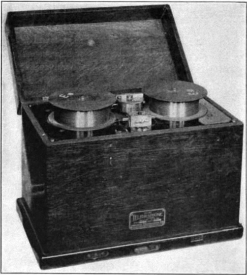
At the 1900 Exposition, Valdemar Poulsen's Telegraphone — the first magnetic sound
recorder — won a Grand Prix and recorded the voice of Emperor Franz Josef; that ~10-second
clip survives as the oldest magnetic recording on Earth. World's Fair
We single this one out because, of all the fair "prizes" in this timeline, it's the most
independently documented (Computer History Museum, ITU) — and the artifact itself still
exists. The 1900 fair also left Paris the Grand and Petit Palais, the Pont Alexandre III, and the Gare
d'Orsay. A reminder to hold every medal claim to this standard: a source you can point to, or an honest
hedge.
How it worked — sound written in magnetism
1
Microphone — your voice became a varying electric current.
2
Recording head — that current fed a small electromagnet pressed against a moving steel wire, magnetizing each passing point in proportion to the sound.
3
The wire remembers — the pattern of magnetization stayed frozen along the wire.
4
Playback — running the wire back past a pickup head turned that magnetism into current again, heard through a telephone earpiece.
Grand Prix · 1900steel wire~10 s clip survivesfirst working recorder
Oberlin Smith published the idea in 1888 but never built it — Poulsen made the first working machine. The 1898 prototype wound piano wire around a brass cylinder; the 1900 Paris exhibits used wire or steel band on spools. The Franz Josef clip survives at the Danish Museum of Science & Technology.
Image: a Poulsen magnetic wire recorder — the Telegraphone's direct lineage — photographed 1922 · Julius Weinberger · Wikimedia Commons, public domain · Source: Exposition Universelle (1900) (Wikipedia); Computer History Museum; ITU; Danmarks Tekniske Museum
1901+ photo & detail
America's first solar business
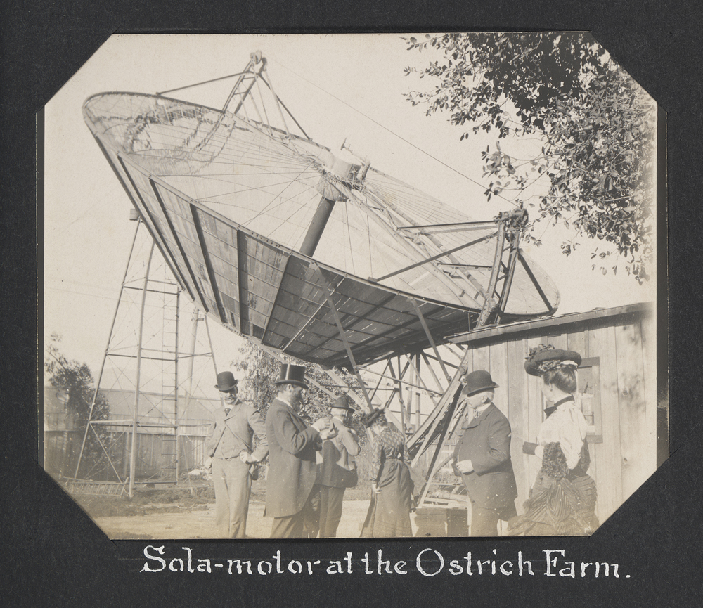
Aubrey Eneas installs a solar motor at the Cawston Ostrich Farm, South Pasadena: a truncated-cone reflector
33 ft across, 8,300 lb, 1,788 pieces of mirrored glass, boiling water at the focus to
run a steam pump.
This is a real photograph of it: a truncated cone lined with nearly 1,800 mirror segments, towering over
top-hatted visitors, focusing the sun onto a boiler at its mouth to pump irrigation water. Eneas's Solar
Motor Company sold several units — until desert hail and windstorms, not the physics, wrecked the
machines and the business.
How the whole system worked
1
Collector — a sun-tracking truncated-cone reflector ~33 ft across the mouth, lined with ~1,788 mirror-glass segments.
2
Boiler — the mirrors threw the sun onto a boiler hung at the cone's focus, flashing water to steam.
3
Engine — that steam ran a small (~10 hp) steam engine.
4
Output — the engine drove a pump lifting well water for irrigation.
33 ft reflector1,788 mirrors~8,300 lb~10 hp
Eneas's company advertised enormous pumping rates (a "1,400 gallons a minute" figure circulated on trade cards) — far beyond a ~10-hp engine at any useful lift — that power moves that much water barely 8 m even at perfect
efficiency, and real pumps are not perfect — so read those flow rates as promotion, not measurement.
Image: "Sola-motor at the Ostrich Farm," c.1901 · Wikimedia Commons, no known restrictions · Source: HistoryNet
1904+ photo & detail
The Pyrheliophoro — St. Louis World's Fair
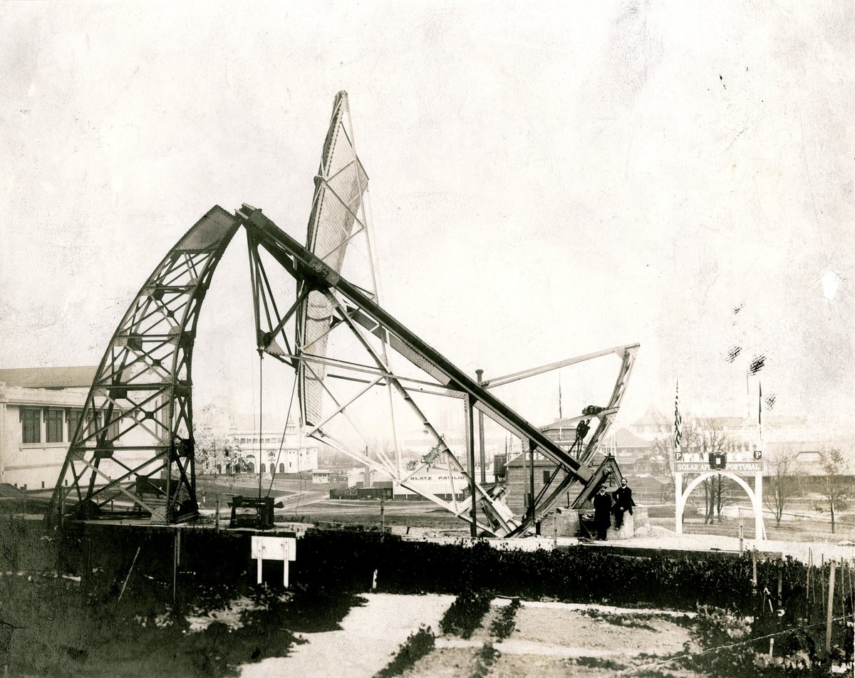
Portuguese priest-inventor Father Himalaya unveils a parabolic concentrator 13 m high with
6,117 mirrors over 80 m², on clockwork sun-tracking, focusing the sun into a 15 cm spot. Portuguese and
period accounts credit it with a Grand Prize plus two gold and one silver medal (Wikipedia
lists the two gold and one silver, without the Grand Prize). The museum's own caption claims a focus of
7,000 °F (~3,870 °C) — a contemporary figure, never independently re-measured.
World's Fair
This is the actual machine, photographed at the 1904 Fair: it stood outdoors on the
high ground southwest of the Palace of Forestry, Fish and Game (entered for judging under the Department of
Liberal Arts), tracking the sun on a clockwork mount and bundling the light of 6,117 little mirrors into a
spot fierce enough to melt metal — a genuine sensation at the same Fair whose grand architecture lives in
the 1800s archive this project grew from.
How it worked — a solar furnace, not an engine
1
Mirror array — 6,117 small glass mirrors (each ~123 × 98 mm) tiled an off-axis parabola of ~80 m² aperture — the glass itself totals ~74 m², so the two figures in the period sources don't quite reconcile.
2
Clockwork tracking — a clock movement turned the whole array to follow the sun across the day.
3
Focus — the light bundled to a ~15 cm spot about 10 m out, onto a magnesia-lined crucible (~45 × 60 cm).
4
Result — heat enough to melt iron in under a minute and fire-clay in ~3 minutes. It generated no power; it was built to prove how hot concentrated sunlight could get.
6,117 mirrors~80 m² reflector15 cm focus @ ~10 m~3,800 °C (est.)
The ~3,800 °C / 7,000 °F figure was a period estimate, never independently measured (sources cluster 3,500–4,000 °C) — and it exceeds what the modern Odeillo furnace reaches, which is itself reason to read it as a claim rather than a measurement. The melting observations — iron, fire-clay, magnesia — are the solid evidence.
Image: "Father Himalaya's Pyrheliophor," 1904 · Missouri History Museum (glass-plate neg. D80435, no. 141547), public domain, via Wikimedia Commons · Source: Missouri History Museum LPE collection; Pyreliophorus (Wikipedia EN/PT); Serra & Rodrigues, ConSolFood 2018
1913+ photo & detail
Shuman's solar plant pumps the Nile
American engineer Frank Shuman builds the first commercial-scale solar plant at Maadi,
Egypt — five ~60-metre parabolic troughs focusing sunlight onto matte-black boilers to
pump Nile water for cotton irrigation. His earlier demo plant made 600 lb of steam an hour and pumped
3,000 gallons a minute.
Shuman was the closest the world came to a solar future before oil. His Sun Power Company's troughs were
the direct ancestors of today's parabolic-trough CSP plants, and he openly proposed covering the Sahara
with them to power the world. World War I scattered his engineers; he died in 1918; the plant was scrapped
for parts.
How the whole system worked
1
Troughs — five sun-tracking parabolic-trough mirrors, each ~60 m (204 ft) long and ~13 ft wide, spaced apart so they wouldn't shade each other.
2
Absorber — each trough focused a line of sun onto a long matte-black boiler tube running down its focus.
3
Steam — the tubes boiled water into low-pressure steam.
4
Pump — the steam ran an engine driving a pump that lifted roughly 6,000 gallons (~23,000 L) of Nile water a minute for cotton fields.
5 troughs60 m each~6,000 gal/min1913 · Maadi
The "600 lb of steam an hour / 25 hp / 3,000 gpm" numbers belong to Shuman's earlier 1910 test plant at Tacony, Philadelphia (572 "hot-box" collectors), not to Maadi. All are period figures from Shuman's own reports, never independently re-measured.
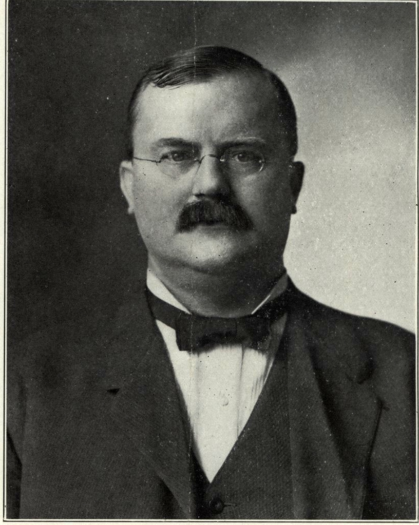
Image: Frank Shuman, portrait · Wikimedia Commons, CC BY-SA 3.0 · Source: Harvard Business School working paper 12-105; The National; Ragheb, solar-thermal history
1915+ photo & detail
Sunlight as spectacle — the Tower of Jewels
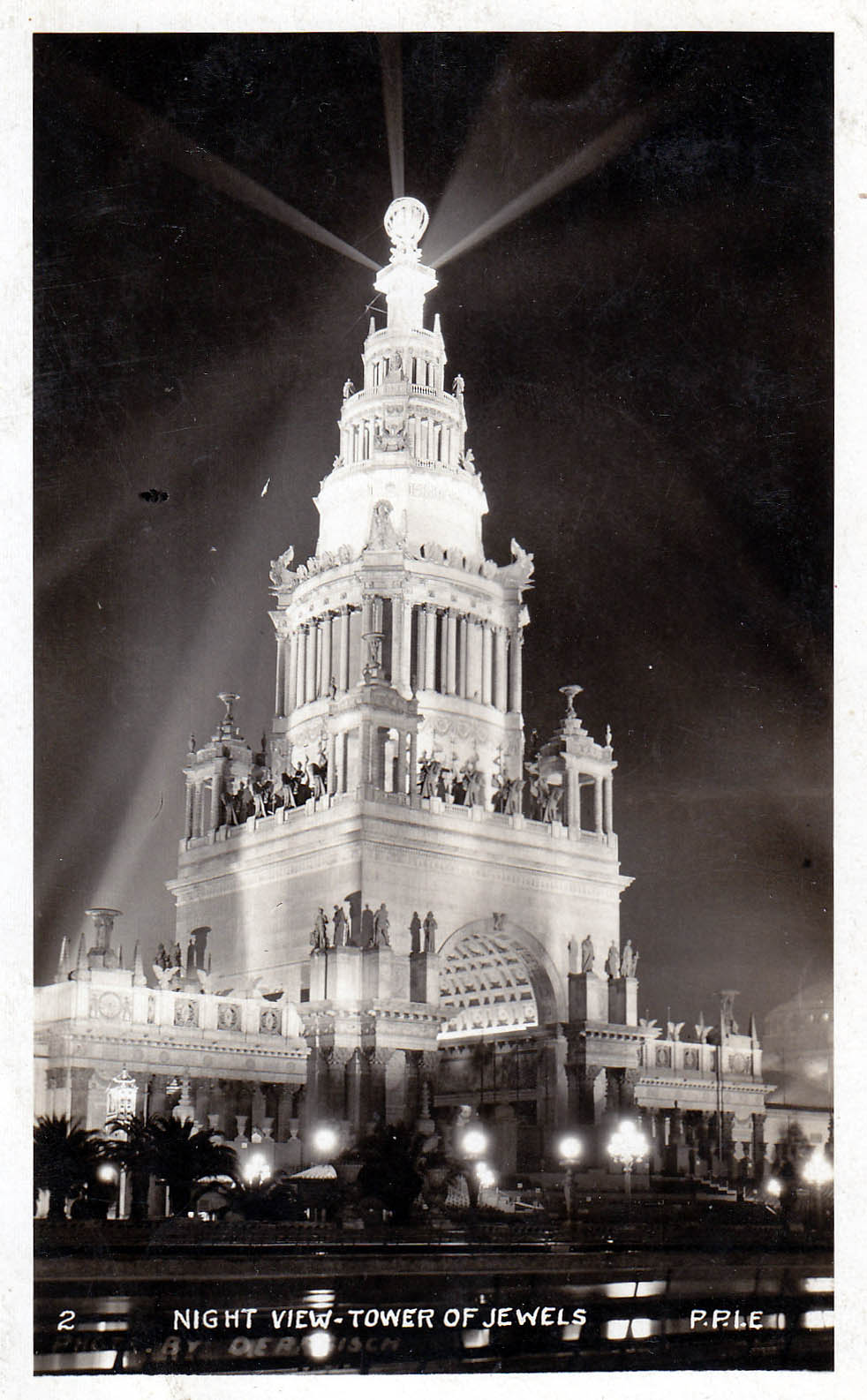
San Francisco's Panama-Pacific Exposition crowned itself with a 435-ft Tower of Jewels
hung with over 100,000 cut-glass "Novagems" that caught and refracted the sun by day and
blazed under 50-plus searchlights by night. A whole building dressed to throw light.
World's Fair
It's the closest the fair era came to this project's own image — thousands of little lenses
across a structure, turning a building into an instrument for light. (Honesty note: the Tower was an
architectural centerpiece, not a prize-winner — and the "102,000 gems / 54 searchlights" counts come from
the fair's own promoters, never independently re-counted.) The Palace of Fine Arts from this fair still
stands in San Francisco today.
How it was built & lit
1
Skeleton — a wood-and-steel armature, 435 ft tall.
2
Skin — clad in "staff," the plaster-and-fiber material used for every temporary palace at the fair.
3
The jewels — about 102,000 mirror-backed Austrian cut-glass "Novagems," hung loose so they swung in the breeze, refracting sunlight into color by day.
4
Night — Walter D'Arcy Ryan aimed 50-plus searchlights at the tower, and the mirror-backed gems threw the beams back as a shimmer of light.
435 ft tall~102,000 Novagems50+ searchlightsstaff over steel
The 102,000 count is a promoter's figure (an older archive says "more than 90,000"), never re-counted; the gems were suspended, not surface-mounted, so the popular "1-7/8-inch jewel covering" detail is wrong. The tower was demolished in 1916, so 435 ft is a design figure.
Image: the Tower of Jewels illuminated at night, 1915 · Wikimedia Commons, public domain · Source: Tower of Jewels & Panama–Pacific International Exposition (Wikipedia); PCAD (Univ. of Washington); NPS; Smithsonian
1918+ detail
The lights go out — for economic reasons
World War I scatters the engineers; the Maadi plant is dismantled for parts; Shuman dies in 1918. Then
coal and oil prices collapse in the postwar recession and again after 1929.
Solar wasn't beaten in the lab — it was undercut at the pump.Lost, not stolen
This is the crucial point for credibility: there was no technical defeat. The machines
worked. They were simply out-competed by suddenly cheap, abundant fossil fuel — and the few champions
died or went to war. For two generations, the economics of cheap coal and oil buried a working technology.
That's the honest story, and it's far stronger than any tale of suppression.
It is also a pattern worth naming: a technology can work, be published, and still
go missing — no villain required. The same decades produced another line of energy research that
went quiet, and I keep it under the same rules as this timeline: cite the source, mark
the hypothesis, claim nothing the evidence hasn't earned. Why it went quiet I
can't yet show, so I don't claim it went quiet for the same reason this did.
The magnetics thread, in Field Notes →
Source: Harvard Business School working paper 12-105 (Jones & Bouamane)
Today+ photo & detail
The same principle, at gigawatt scale
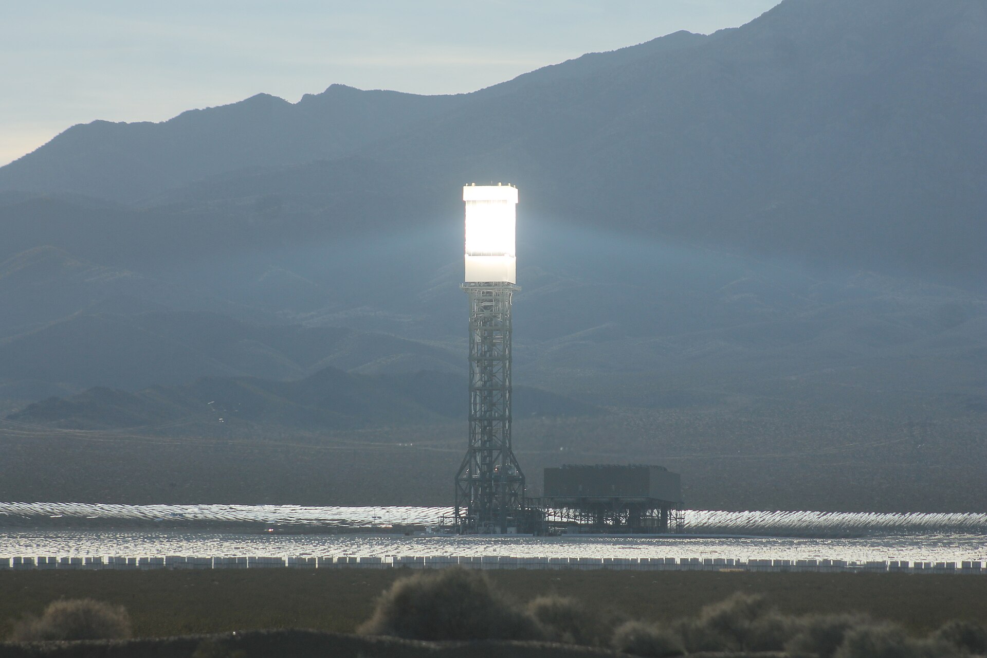
Concentrated Solar Power runs right now: the Odeillo solar furnace reaches ~3,500 °C; California's Ivanpah
is a ~392 MW solar-tower plant in its final year; molten-salt plants like Crescent Dunes and Morocco's Noor/Ouarzazate store
the sun's heat (~565 °C) to make power after dark. Sun → heat → steam → electricity is
mature, deployed, and bankable.
This is Ivanpah in California — 173,500 heliostats aiming sunlight at boilers atop three towers, exactly
Adams' 1878 heliostat idea at industrial scale. The principle never changed; only the economics did. The
future-cathedral vision is the same machine, brought home to the grandest structures we ever built.
How the whole system works
1
Heliostats — 173,500 sun-tracking mirror units aim sunlight at the tops of three towers.
2
Receiver boiler — the concentrated light heats water in a tower-top boiler directly to ~550 °C superheated steam.
3
Turbine — that steam drives conventional steam turbines (Siemens SST-900).
4
Grid — ~392 MW gross. Ivanpah has no heat store, so it runs only in daylight.
5
After dark — molten-salt plants (Crescent Dunes; Morocco's Noor) instead heat salt to ~565 °C and store it, running the turbine for hours after sunset.
173,500 heliostats~550 °C steam~392 MW gross~565 °C salt
Exactly the 1876 boiler and the 1878 mirror, scaled up: sun → heat → steam → power. Only the size and the economics changed. (Ivanpah is slated to close in 2026; these are its design specs.)
Image: Ivanpah Solar Electric Generating System · Wikimedia Commons, CC BY-SA 4.0 · Source: Ivanpah, Odeillo, Ouarzazate (Wikipedia); Bechtel; U.S. DOE; California Energy Commission
The Physics · Made Simple
How the light becomes power
No exotic science — just optics you can prove with a magnifying glass on a sunny day.
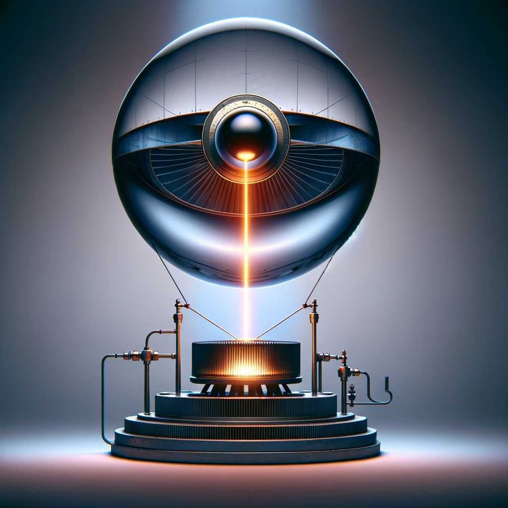
The machine. A spherical lens gathers sunlight and concentrates it into a single intense beam
that strikes the receiver below — boiling water into the high-pressure steam that drives the generator.
Everything else in this project is built around this one device. Drive Mind AI concept render · Brad Harris
1
Gather
A lens or curved mirror collects sunlight over a wide area and bends it toward one point.
2
Concentrate
All that light piles onto a tiny focal spot — the "heat point" — driving its temperature up.
3
Boil
The heat point sits on a black receiver full of water (or salt). It boils into high-pressure steam.
4
Power
Steam spins a turbine/generator — electricity — then condenses and runs the loop again.
First principle: concentration is temperature
Sunlight spread thin is gentle warmth — a black plate left in the open sun tops out around 80 °C — too hot to
touch, nowhere near hot enough to drive a machine. Gather that same sunlight from a wide area and pile it onto a small spot, and the temperature climbs with
how hard you concentrate it. That is the whole engine: the sphere's only job is to make one spot
hot enough to be useful.
~80 °C
a flat black plate in open sunlight — useful warmth, but no more
100s °C
tens of "suns" concentrated — enough to boil water into driving steam
3,500 °C
the Odeillo solar furnace, ~10,000 suns — hot enough to melt almost anything
The glass sphere
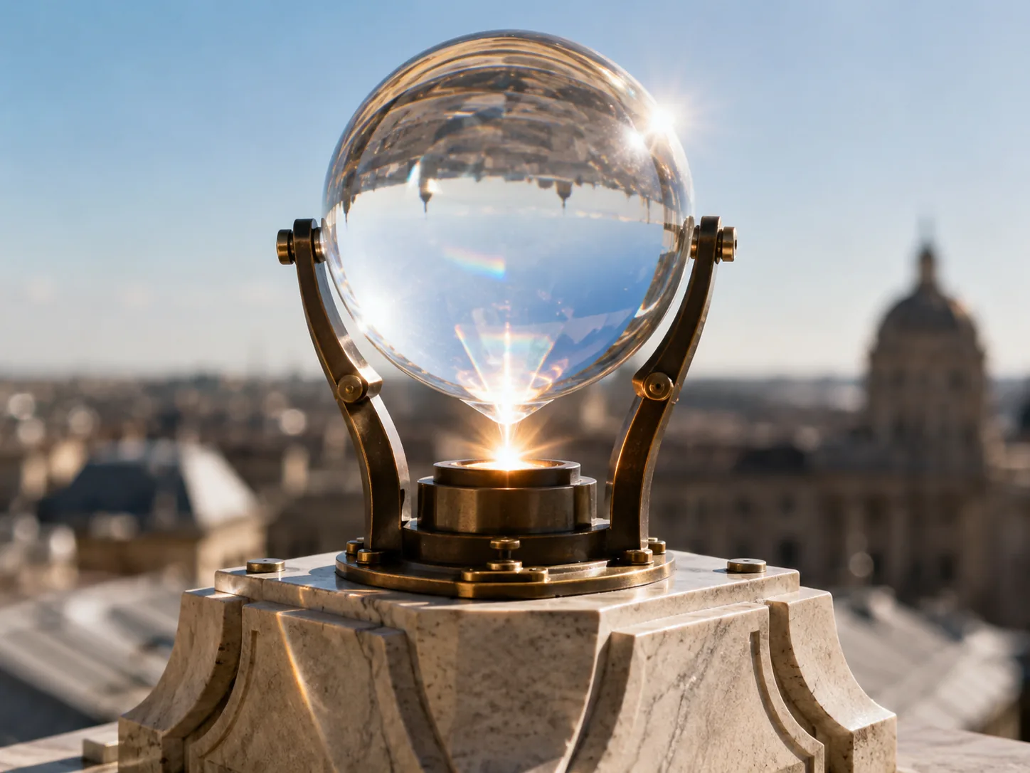
A clear solid ball is a real burning lens. It collects sunlight across its whole face and bends it twice — once
entering the glass, once leaving — folding it into a tight, blazing focal region just behind itself. A bigger
sphere simply gathers more total power. Where that focus lands follows simple, settled optics:
Ball-lens focal length: f = n·D / [4(n − 1)] — for ordinary glass (n≈1.5)
the focus lands about half a radius behind the sphere; for high-index glass (n≈2) it focuses right at
the surface.
The whole machine in one picture: parallel sunlight is gathered by the sphere and folded onto a
receiver plate — the hottest point in the system — whose heat then passes
down into the building's thermal mass. (Concept diagram.)
The plate sits at a fixed depth
Here is the quietly powerful part. The focus doesn't wander as you change the size of the sphere — it stays
at the same fraction of the radius, set only by the glass itself. A marble and a
two-metre orb of the same glass focus at the same proportional spot. So you design the
receiver plate once and scale the whole building around it: whatever the size of the
sphere, the plate that drinks the light belongs in the same place.
And because a sphere never quite focuses to a mathematical dot — the outer rays bend a touch too hard, so the
focus is an intense region, not a pinpoint — a flat plate is exactly the right receiver.
You want fierce heat spread across a surface you can plumb, not a hole drilled into a single point.
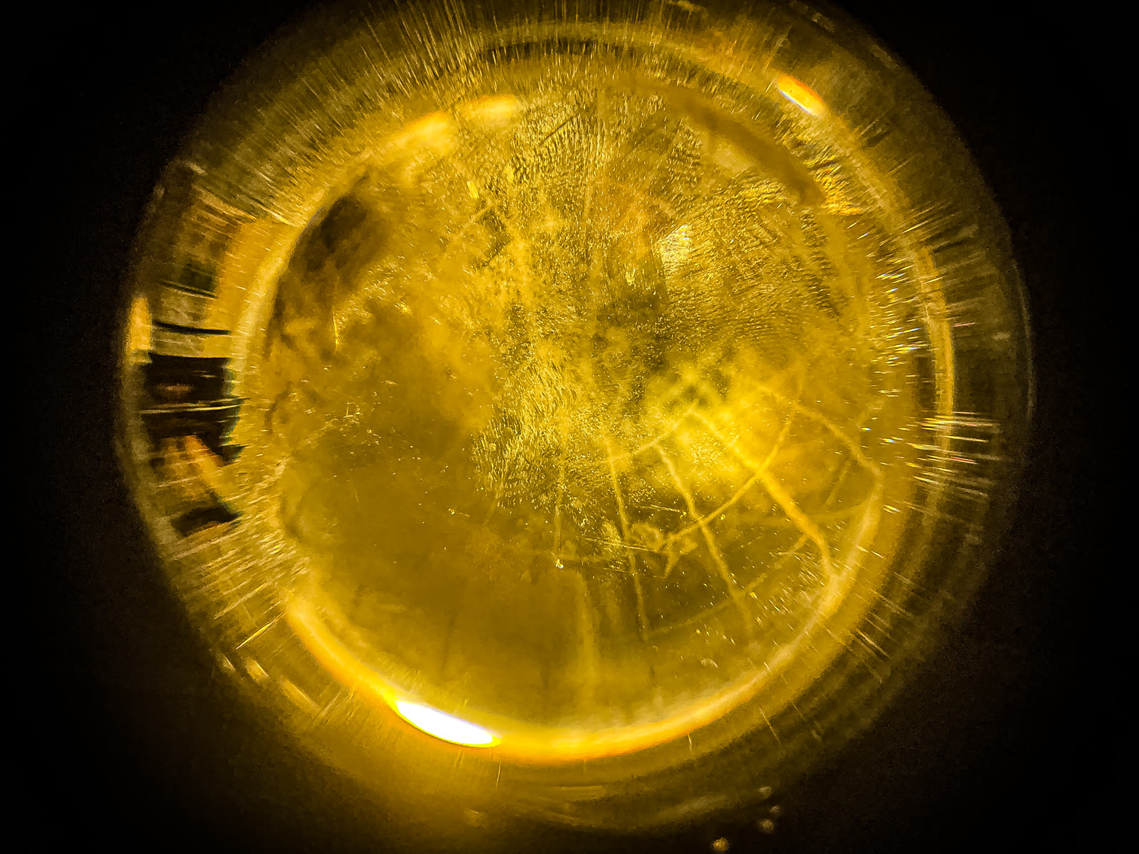
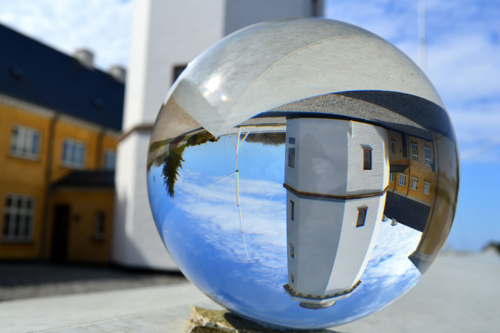
Light folded and concentrated inside a real glass sphere — the same effect, scaled up, is the
furnace. Photo: Jalfyn Benging · CC BY 4.0
Inside the receiver: heat, air & water
The plate isn't a solid lump — it's a working block with three jobs stacked beneath the focal point. The light
makes the heat at the top; everything below decides where that heat goes.
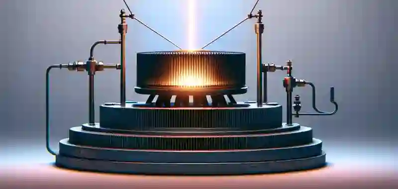
The receiver block sits directly under the focal point. The finned core takes the concentrated light and
glows; a small fan beneath it pushes the heat down into the building — the one place buoyancy will not do the
work, since hot air rises — while the copper water lines either harvest that
heat or carry it away to cool the plate. Drive Mind AI concept render · Brad Harris
1
The heat plate
The finned core sits at the focus and turns concentrated light into fierce heat — the hottest point in the whole machine.
2
The fan
Beneath it, a fan pulls the hot air off the fins and pushes it down into the wall and floor channels. The temperature difference can even drive it on its own — no fuel, like a solar chimney.
3
The water loop
Copper lines wrap the core. Run them one way and they harvest the heat as hot water or steam; run them the other and flowing water carries heat away to cool the plate on demand.
The water line is also the safety valve. Concentrated sunlight is a genuine fire hazard, so the receiver is
never left to run away. If the plate climbs too hot, the system flushes water through the core to carry
the heat off fast — the same plumbing that harvests heat becomes the brake that cools it, paired with shading or
de-focusing the sphere. Heat that isn't wanted is never wasted or dangerous: it's banked in the mass, or dumped to
cool.
A whole landscape bent to a focus inside a glass ball — you can see a sphere gather and
concentrate light. Photo: Ragnar1904 · CC BY-SA 4.0
The heat is banked, not burned
The plate doesn't only make heat for this instant. It drives that heat down into the building's stone, where
it becomes a trapped entity — released slowly over hours, long after the sun has moved on.
Boiling water for steam and power is just one way to spend it; the rest is stored in the
mass and breathed back into the rooms. The sphere is the furnace; the walls are the
radiator.
That this is real isn't theoretical: in January 2024 a decorative crystal ball ignited a pile of towels in a
house in Essex, England, simply by focusing window-light. Multiply that by intent, scale, and thousands of
units — and you have a power plant.
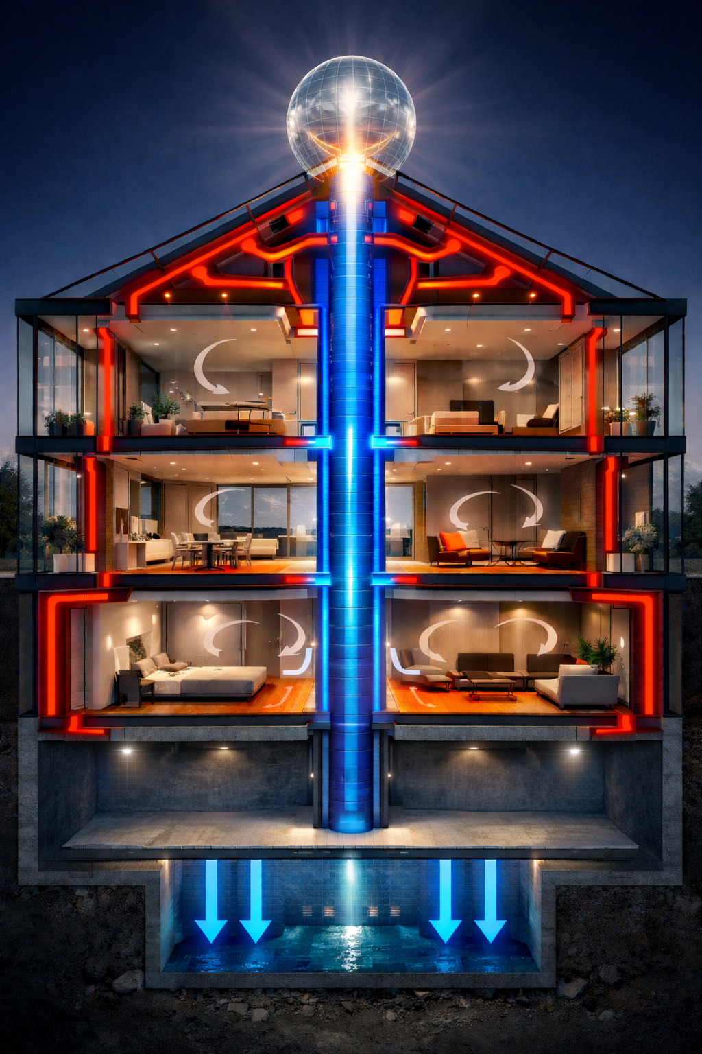
The whole system, end to end
Put both engines together and the building becomes one machine: the sphere gathers the sun and
makes the heat; the receiver hands it to the structure; the outer wall channels
carry it down and the mass banks it, then radiates it back from the walls and
floors. At the bottom the heat runs under the floor — beneath the pool, which it warms from
below, and out under the side patios. Meanwhile cool air is drawn from a
lower level and climbs separate interior pillars — the solid floors block it
from drifting sideways, so the pillars are its only way up — to be dropped into each room near the
top, where it falls, settles, and is then drawn back and recycled. Heat down the outside,
cool down from within — a closed loop the heat itself keeps turning. Everything below is just this picture, part by
part.
The whole system. Heat runs down the outer walls and under the
floor — beneath the pool and out under the patios — and the mass radiates it into the rooms. Cool air is drawn
from a lower level, up the interior pillars, dropped into each room near the top, then returned and recycled —
the whole loop forced by the heat. The two engines are really one machine. (Concept diagram.)
The Second Engine · Heat & Air
Breathing walls: the building as a thermal engine
The lens makes power — but the structure itself does something just as old and just as real. It
stores the sun's heat in its own stone, moves it through channels in its mass, and breathes cool air up from the
earth. Hot from the top, cool from below, distributed through the body of the building.
6–11 h
a thick stone wall delays the day's heat — warmth arrives at night, when you need it (measured in real walls)
≤ 40%
of the outdoor temperature swing reaches inside — the mass flattens the peaks (decrement factor 0.13–0.4)
46 °C
vent air still measured six days after the fire went out, at Malbork Castle's medieval stone heat-store
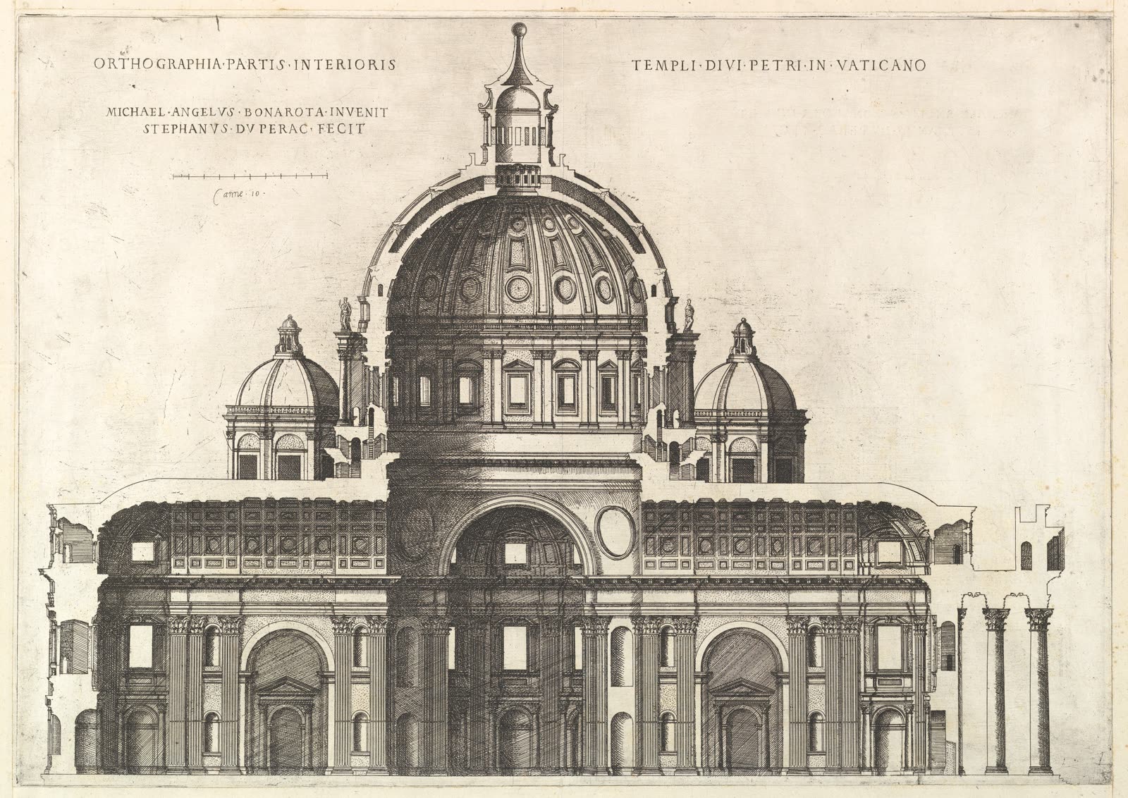
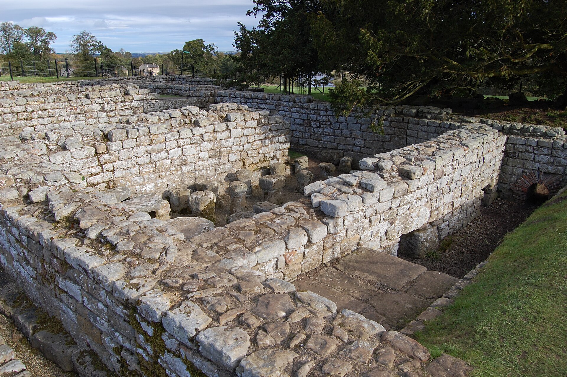
The whole loop, drawn over a real Renaissance section: the rooftop sphere + receiver heat the lantern ·
warm air runs down the outer walls and under the floor · the stone mass
radiates it gently back in · and cool earth-coupled
air rises through the nave from the crypt below. Base engraving: Étienne Dupérac after
Michelangelo, 1569 · The Met · CC0
Channeled heat is 2,000 years old
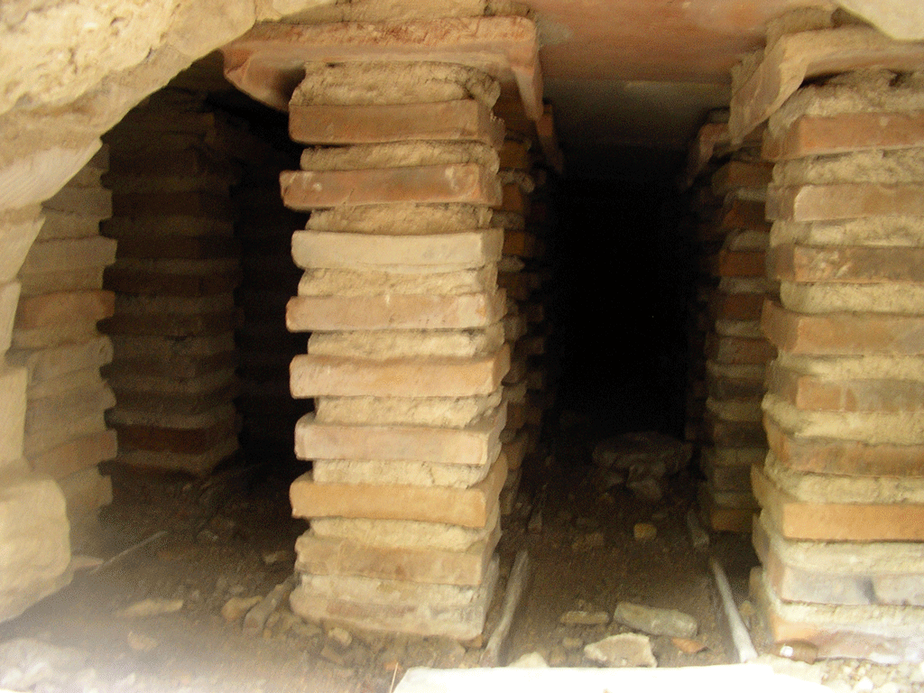
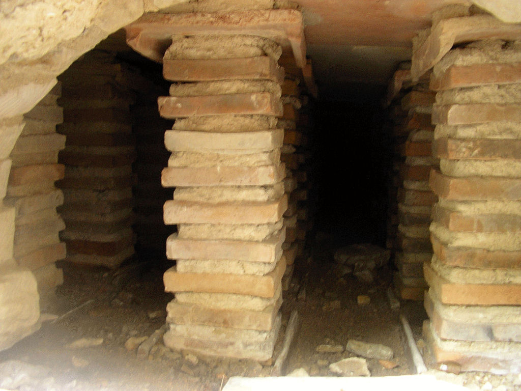
Pushing heat through channels in a building's mass isn't new — it's the Roman hypocaust:
hot air circulated under floors and up through wall flues to warm the whole structure. The idea never died.
Medieval engineers built heat-storage hypocausts — granite piled over a furnace vault that
radiated warmth for days; some 800–1,000 were built across northern Europe. Korea's
ondol and the European masonry stove are the same principle. Modern engineers model the
ideal heat channel at just 50–100 mm wide.
A real Roman hypocaust — the stacked tile pillars are the channels hot air flowed through.
Photo: Justin Deegan, CC BY 3.0
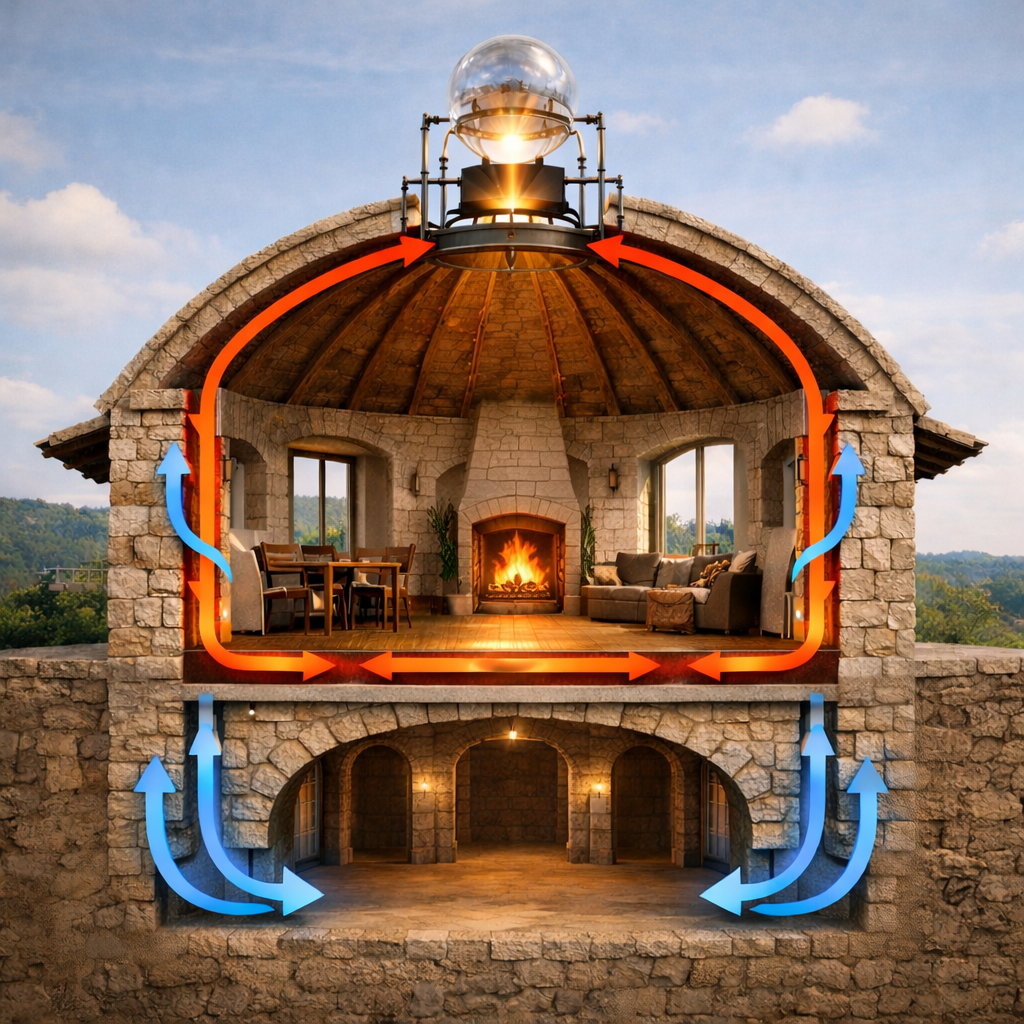
The whole loop in a single dome: the rooftop lens feeds heat down through the stone walls and floor,
the mass holds it and radiates it back, and cool air rises from the vaulted crypt below. (Concept diagram.)
The roof feeds the mass
A rooftop solar collector is the modern furnace. Transpired solar collectors already heat
ventilation air at 60–70% efficiency, raising it ~20 °C on a sunny day. Solar-fed radiant
floors cut a building's heating fuel by 63–89% in climate studies. And the top-hot /
bottom-cool geometry is measured: a passive solar-chimney + earth-tube system moved
252 m³ of air an hour with zero electricity and cut summer indoor temperature by ~9 °C.
Every piece of your loop is independently proven.
Look again at the loop above: the heat doesn't drift through the open rooms — it runs up the corners
and pillars. Each of those is built as an active thermal chamber: a single
solid block of dense stone with a hollow channel cut into its outer face. That placement is
the whole trick. The warm channel sits between the cold outside and the storage mass, so it works as a
living shield — it keeps the block's outer face warm, and any heat that tries to escape has to
push all the way out through the channel before it's lost, while the heat travelling inward soaks into the solid
stone behind and is kept — the warmed stone then radiates gently back into the room. Warm the
channel even a little and the whole block stops leaking. A second hollow, cut into the inner face,
carries the recycled cool air up through the block and releases it into the room near the top —
so one block does both jobs at once: a warm shield outside, a cool supply inside.
This isn't a hunch — it's a measured technique. Buildings with pipe- or channel-embedded
envelopes run a thin warm (or cool) layer inside the wall to intercept heat right at the boundary: studies
show it cuts heat loss through the envelope by 33–84%, and the very same layer can switch
between heating the room and shielding it just by changing the temperature
you feed it. Put the channel toward the cold side, the dense mass behind it, and the wall both
stores more heat and loses far less.
The active thermal chamber: a single solid stone block with two
hollows cut into it — a warm channel in the front (outer) face that shields the cold side and charges the
stone, and a cold channel in the inner face that carries cool air up and releases it into the room at the
top. The solid mass between banks the heat and radiates it back into the room. (Concept diagram.)
The loop drives itself
Heat and cool run on separate paths, and the building is plumbed so each moves on its own.
The sun's heat travels down the outer wall channels, soaks into the mass, and at the base
runs under the floor — warming the pool from beneath and venting out under the side patios.
Cool, earth-tempered air is drawn up from a lower level through the interior
pillars — the solid floors block it from drifting sideways, so the pillars are its only chimney — and is
dropped into each room near the top (about three-quarters up), where, being heavy, it falls
and settles. Once it has done its work it's drawn back into the pillars, returned to the lower
level, re-cooled, and sent round again — a closed loop, recycled rather than dumped. Warm air rising and
cool air falling keep this cool circuit turning with no fan of its own; the heat itself forces
the airflow. The one powered part is the small fan at the receiver, driving heat downward
against its own buoyancy.
Real buildings already run on exactly this. The Barra–Costantini system threads
thermosiphon air channels through concrete floors and ceilings for a 50% solar heating
fraction — built into 40 occupied flats in Marostica, Italy. Thermally-activated slabs
(TermoDeck) pass ventilation air through hollow cores so the mass itself becomes the heat exchanger, and pull
night-cool through those same cores to chill the building by day.
The channels are structural — hot air threads the mass itself, just as in a Roman hypocaust.
Photo: Justexp / Hogweard · CC BY 3.0
The same mass can bank water
Stone is a fine heat store — but water is a better one, and a great structure full of cisterns, basins and pools
is a far bigger battery than the walls alone. Run the warm channels past water and the building becomes a
water heater as well as a radiator.
~2×
water banks roughly twice the heat of stone or concrete, litre for litre (4.18 vs ~2.0 MJ/m³·K)
10 ≈ 21 cm
a 10 cm depth of water holds as much heat as a 21 cm wall of solid concrete
70–90 °C
what a salt-gradient solar pond holds for months — a different trick from heating a pool, and kept distinct below
And a pool is happiest heated from below. Warm the thermal mass beneath the water and the heat
lifts into the pool on its own — warmer water is lighter, so it rises through the cooler water above by natural
convection, with no pump and no piping forcing it. The mass holds the heat; the water simply receives what floats
up. (Water carries heat through itself slowly — far slower than stone conducts — but this buoyant overturning from
beneath does the distributing for free.) Large bodies of water make superb seasonal banks: a salt-gradient
solar pond stores the sun's heat at 70–90 °C for months, and the same water that banks the heat
can be drawn straight off as hot water.
A pool heated from below: warm the mass beneath the water and
buoyancy carries the heat up through the pool on its own — no pump. The pool banks the heat and gives back hot
water. (Concept diagram.)
One hard rule: it has to be real mass. None of this works in a hollow, lightweight building. The whole
engine depends on the walls being heavy — stone, brick, dense concrete, rammed earth: materials
with a high heat capacity and a slow, deep thermal lag. The delay a wall buys you is roughly its
thickness divided by the square root of how fast heat diffuses through it — which is why a thick
masonry wall pushes the day's heat 6–11 hours into the night and flattens the swing, while a thin stud wall stores
nothing at all. The architecture is the machine, so the material must be chosen and sized as a
thermal-mass material on purpose.
Why build the channels into the walls and floors? Because it turns the whole structure into one gentle,
even radiator. Instead of blasting hot air from vents — with its noise, its drafts, and its hot-and-cold
spots — the warmth travels through the building's own mass and reaches every room evenly. The stone soaks up the
heat and releases it for hours after the sun is gone, so the temperature stays steady day and night. There's no
bulky ductwork to hide, and no blowers pushing air through the rooms — only the small fan at the receiver. It is simply the most efficient way to spread low-grade
solar heat through a massive building — warmth woven into the walls, coolness drawn up from the earth below.
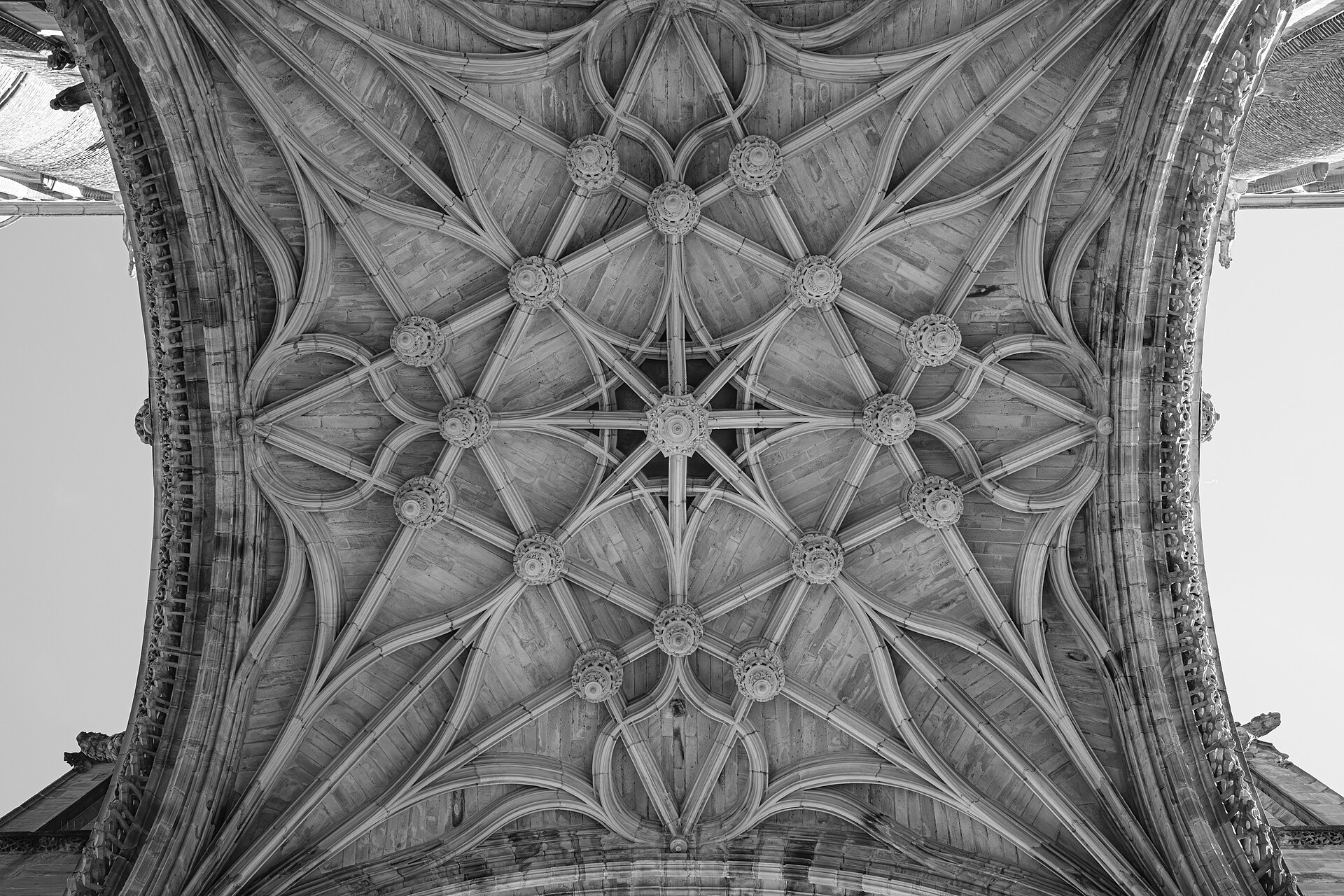
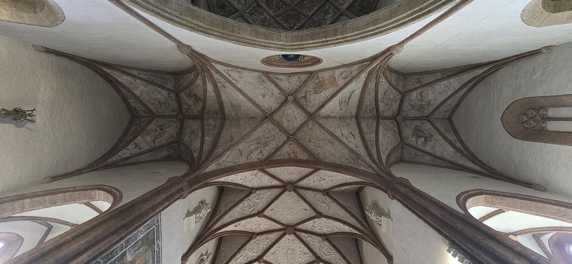
Gothic vault — the mass overheadMarc-Julien Photography · CC0Rib-vaulted ceilingQwertzu111111 · CC BY-SA 4.0The same loop in any structure (concept)Hypocaust channels, in stoneSteven Fruitsmaak · Public domain
Skeptic-Proof
The honest ledger
A serious vision says what's solid and what's hard. This is the difference between a manifesto and
a fantasy.
✓ Proven & bankable
Lenses and mirrors concentrate sunlight to extreme heat — textbook optics, demonstrated for 250 years.
Sun → heat → steam → electricity runs today at gigawatt scale (CSP).
Massive masonry stores solar heat and releases it for hours (thermal mass / Trombe walls).
Channeled mass distributes that heat by natural circulation — Barra–Costantini reached a 50% solar heating fraction in 40 real flats; TermoDeck slabs do it commercially.
Active channel-embedded walls cut envelope heat loss 33–84% (measured); water banks ~2× the heat of concrete, litre for litre.
△ Hard & honest
A sphere's focus is a blur, not a pinpoint (spherical aberration) — so we catch it on a sized receiver plate, never a fictional dot. Bigger gathers more power; mirrors still focus tighter.
Concentrated sunlight is a genuine fire & glare hazard — so the receiver is water-cooled with shading and defocus/shutoff, never left to run away. Designed for, not waved away.
An active warm-shield channel is not free insulation — it spends stored heat to save more, and only nets out when there's surplus heat to run it.
Water stores more but brings its own costs — containment, freezing, corrosion — and a long-term solar pond traps heat at the bottom, the opposite of heating a pool from below. Two different tricks, kept distinct.
A rooftop array on a real cathedral covers only ~22–25% of its energy — the win is in reducing demand, not one magic sphere. (And the Archimedes "death ray" is a myth — MIT & MythBusters — we don't lean on legends.)
How We'd Build It
Pre-engineered: built to a kit
These aren't carved one-off by hand. The whole cathedral is a kit of stone parts —
piers, springers, voussoirs, ribs, vault webs, floor slabs and dome rings — cut off-site and assembled like
precast. And the oldest idea in the book does the structural work: the arch.
An arch carries its load as pure compression, running down a curved path called the
thrust line — an inverted catenary. Each wedge block (a voussoir) leans on
the next; the keystone locks the ring. With masonry, stability, not strength,
governs — so the shape itself is the engineer. Get the curve right and the stone simply
stands — in pure compression, no steel ties, exactly as the great cathedrals stood for
centuries. Today that's not guesswork: the voussoirs are cast and then CNC-milled to the exact taper, and the
modern structural-stone revival proves prefab stone is back as a real building system (15 Clerkenwell Close;
Webb Yates & the New Stone Age).
One arch as a full order: piers, springers, eight voussoirs and a
keystone, on a fused clear-stone base with low-friction seismic-isolation bearings. Every block is cored for the
airflow loop and cast with self-healing lime clasts. (Concept blueprint.)
Spin that arch around a center and it becomes a dome — the same compression logic in the round.
Rings of voussoirs stack into a shell, meridional ribs run crown to base, and an oculus compression
ring locks the top — the very place the sphere and receiver sit:
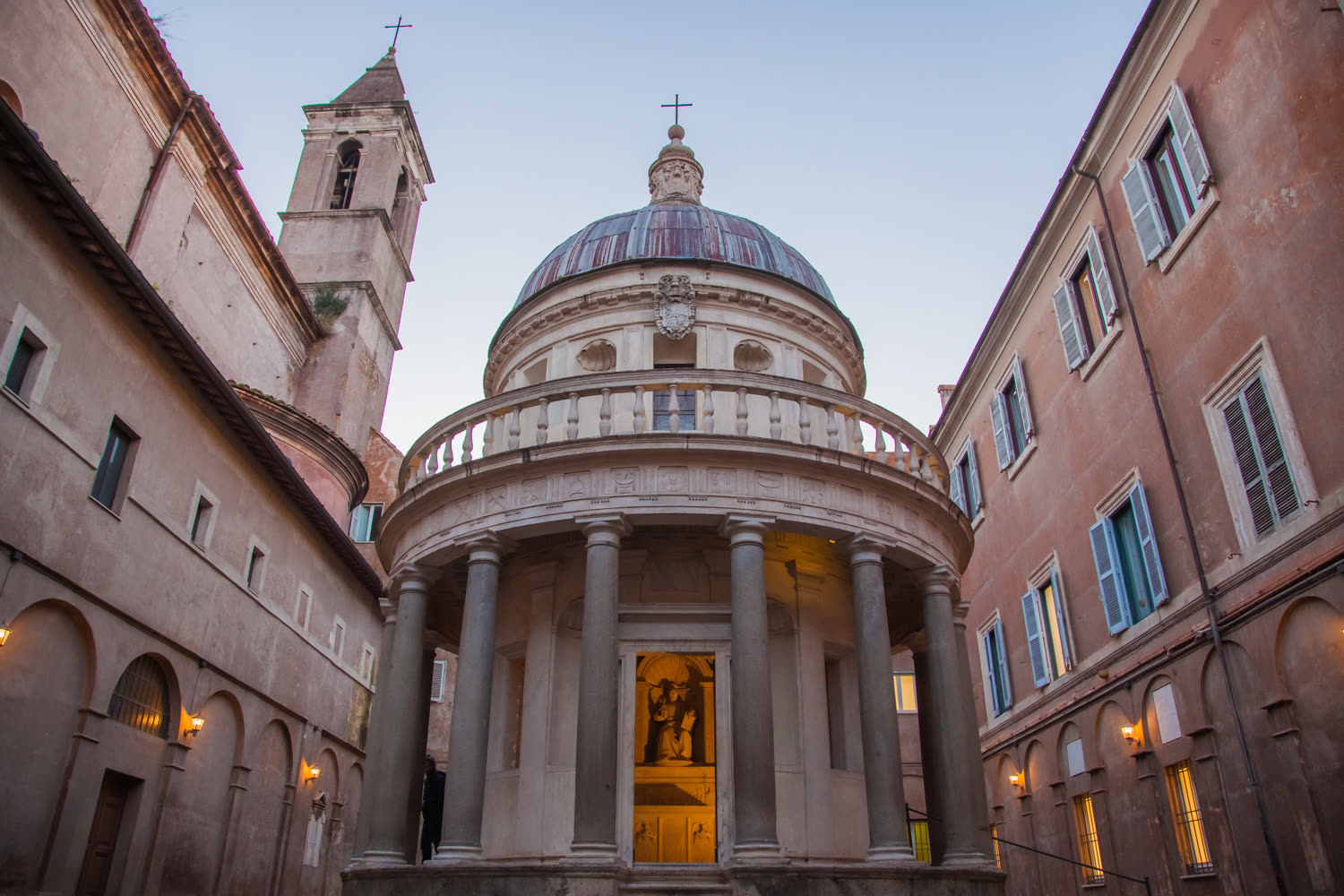
A real pillared dome — Bramante's Tempietto, Rome (c.1502): a ring of
16 columns carrying a drum, dome and lantern. The form, made buildable as a kit. Photo: Bradley Weber · CC BY 2.0Built to a kit — every block, one order, each with its cut angle
and count. Pure compression, no steel ties; every block cored for the airflow loop and cast with self-healing
lime clasts.
Two more pieces make it durable and quiet. The blocks are cast with lime clasts, so a hairline
crack heals itself when water reaches the reactive lime — the mechanism MIT identified in Roman concrete in 2023.
And the building sits on a fused "clear-stone" base made with the lens itself (concentrated
sunlight vitrifies silica into glass — see the Solar Sinter). Clear stone is tremendously strong in
compression, which makes a superb hard foundation; the earthquake trick isn't the stone
"absorbing" the shock (glass is brittle) but base isolation — the whole structure rides on
low-friction bearings and gently slides, cutting the force that reaches it. Honest, and stronger for it.
And the same logic scales to the whole building. Here is a single bay as a complete order —
every block, its cut angle, and how many — from the rooftop sphere down to the isolation bearings:
One cathedral bay as a full order — every block keyed to a cut angle
and a count, from the rooftop sphere to the isolation bearings. Pure compression, no steel ties; every block
cored for the airflow loop and cast with self-healing lime clasts. (Concept blueprint.)
Every pillar is a dual channel; every arch is a duct
In the cathedral the airflow isn't bolted on — it runs through the bones. Each pillar is a dual
hot-and-cold channel: the same active-thermal-chamber trick from the walls, carried in a single shaft. A
warm flue on its outer side runs the sun's heat down and keeps the stone charged and shielded;
a separate cool flue on its inner side carries earth-tempered air up from the crypt. One member,
two jobs — a warm spine against the cold, a cool riser for the room — so the structure that holds the roof up is
the same structure that moves the air.
And the arches do the distributing. Where a pier rises into the springing of an arch, the air
turns and follows the curve: the arch and vault rib act as a duct, carrying cool supply across
the top of each bay to drop it where it's wanted, and gathering warm return back toward the next pier. The thrust
line that makes the arch stand and the air path that makes it breathe trace the same curve —
compression overhead, a hollow core within. The vaults become the building's plenum; the colonnade, its lungs.
Why this works — and why it's honest. Threading supply and return air through the structure's own hollow
members is exactly what hollow-core thermally-activated slabs (TermoDeck) already do commercially,
and what Roman wall flues did in masonry two thousand years ago — here the idea is simply turned
vertical into the piers and bent along the arches. It only carries low-grade
warmth and gentle, buoyancy-driven flow — the heat rising, the cool falling — not high pressure; the structure
distributes, it doesn't pressurize. Mass and shape do the work; the curve is both the engineer and the duct.
Sources: Webb Yates Engineers; Architects' Journal & Architectural Record (structural-stone revival); thrust-line & limit analysis (Heyman); MIT/Harvard, Science Advances (2023, self-healing lime clasts); M. Kayser, Solar Sinter (2011); friction-pendulum base isolation (Asian J. Civil Eng., 2024)
The Vision
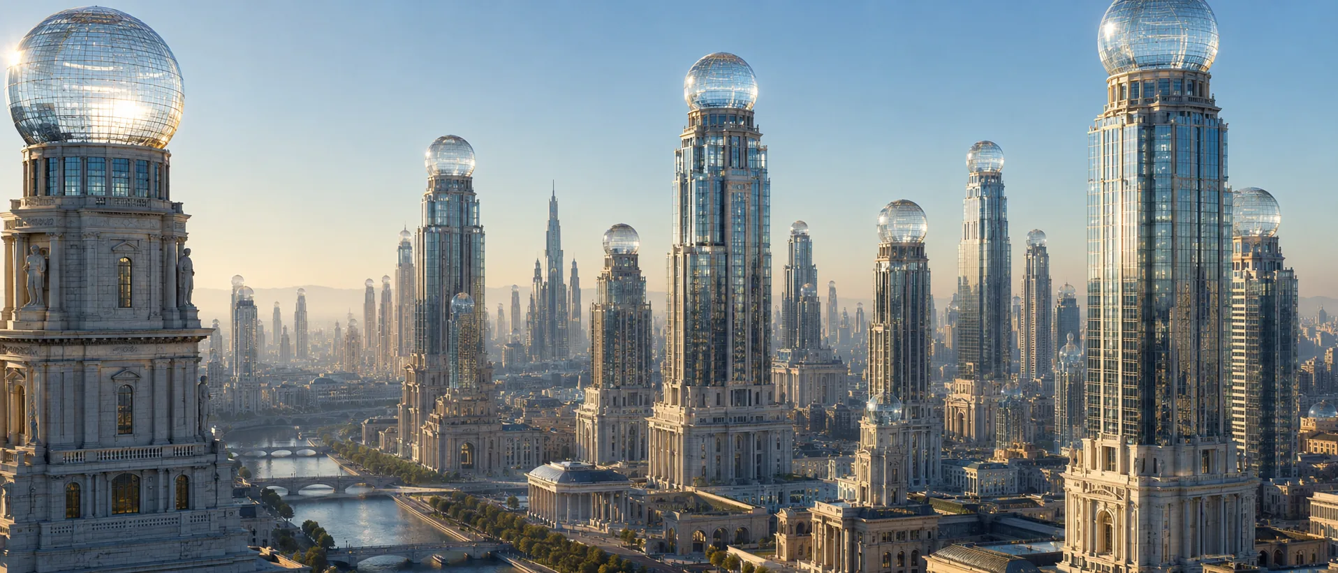
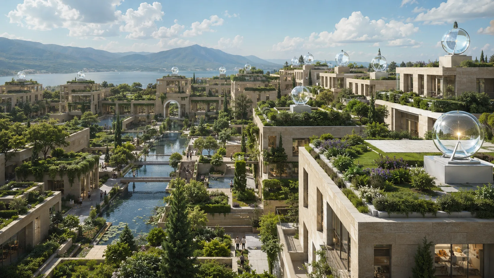
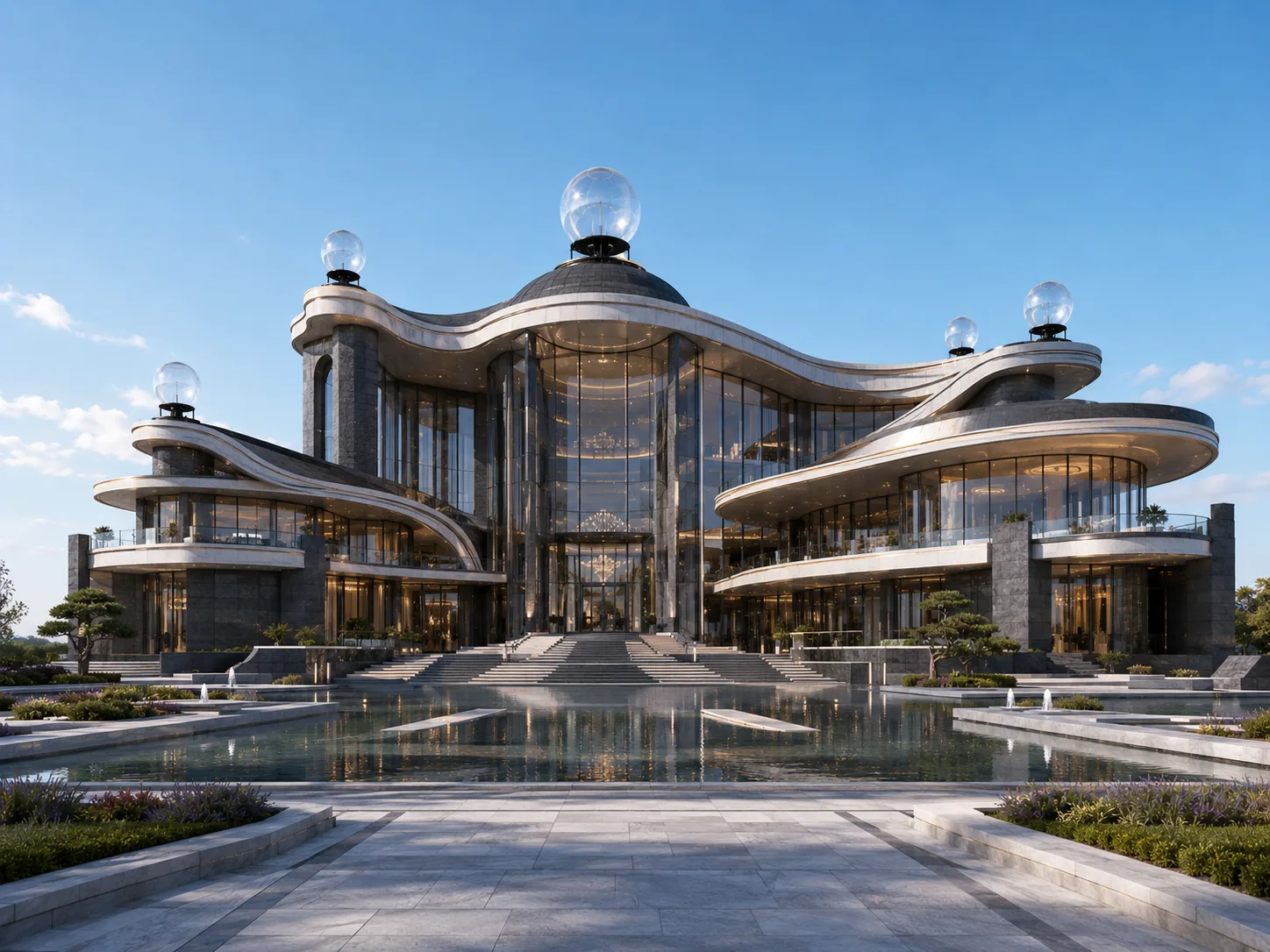
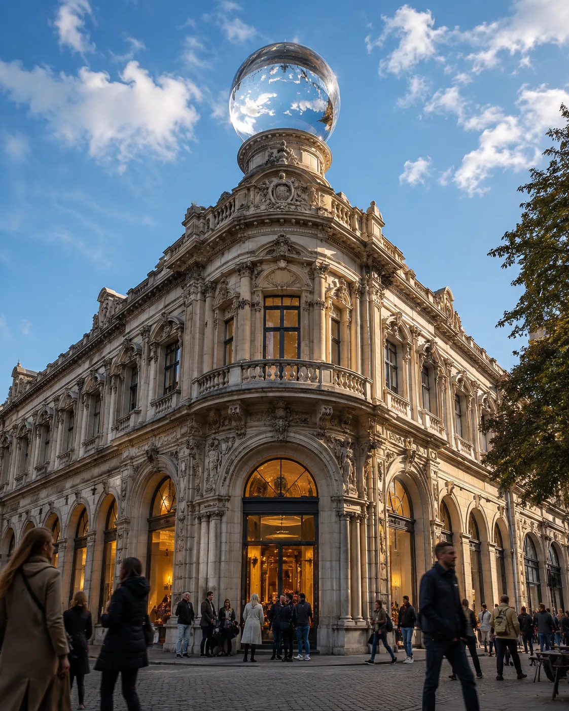
Cathedrals of light
The grandest structures we ever built — stone, masonry, peaks reaching for the sky — reimagined as
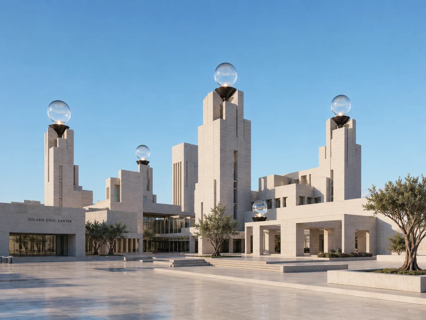
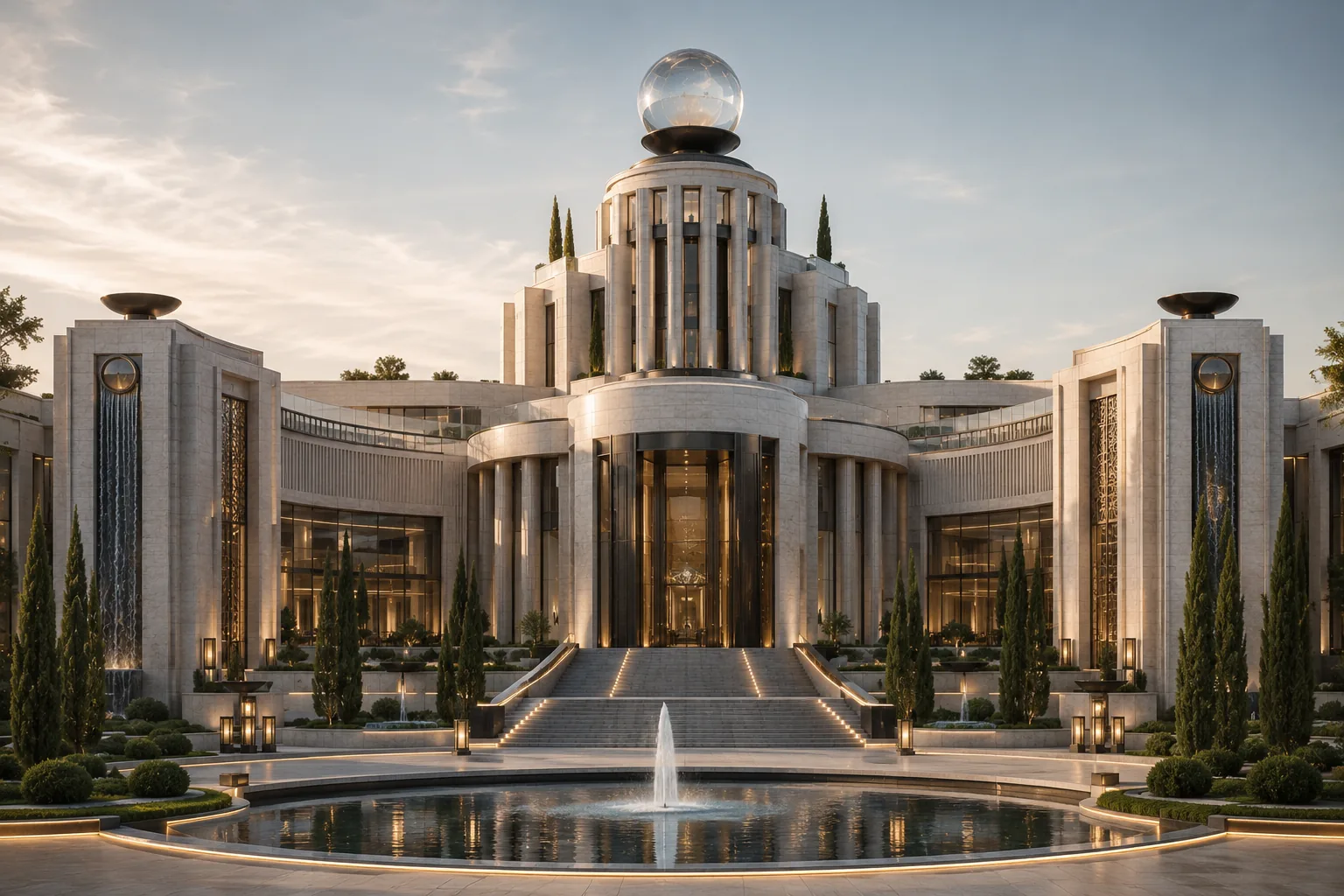
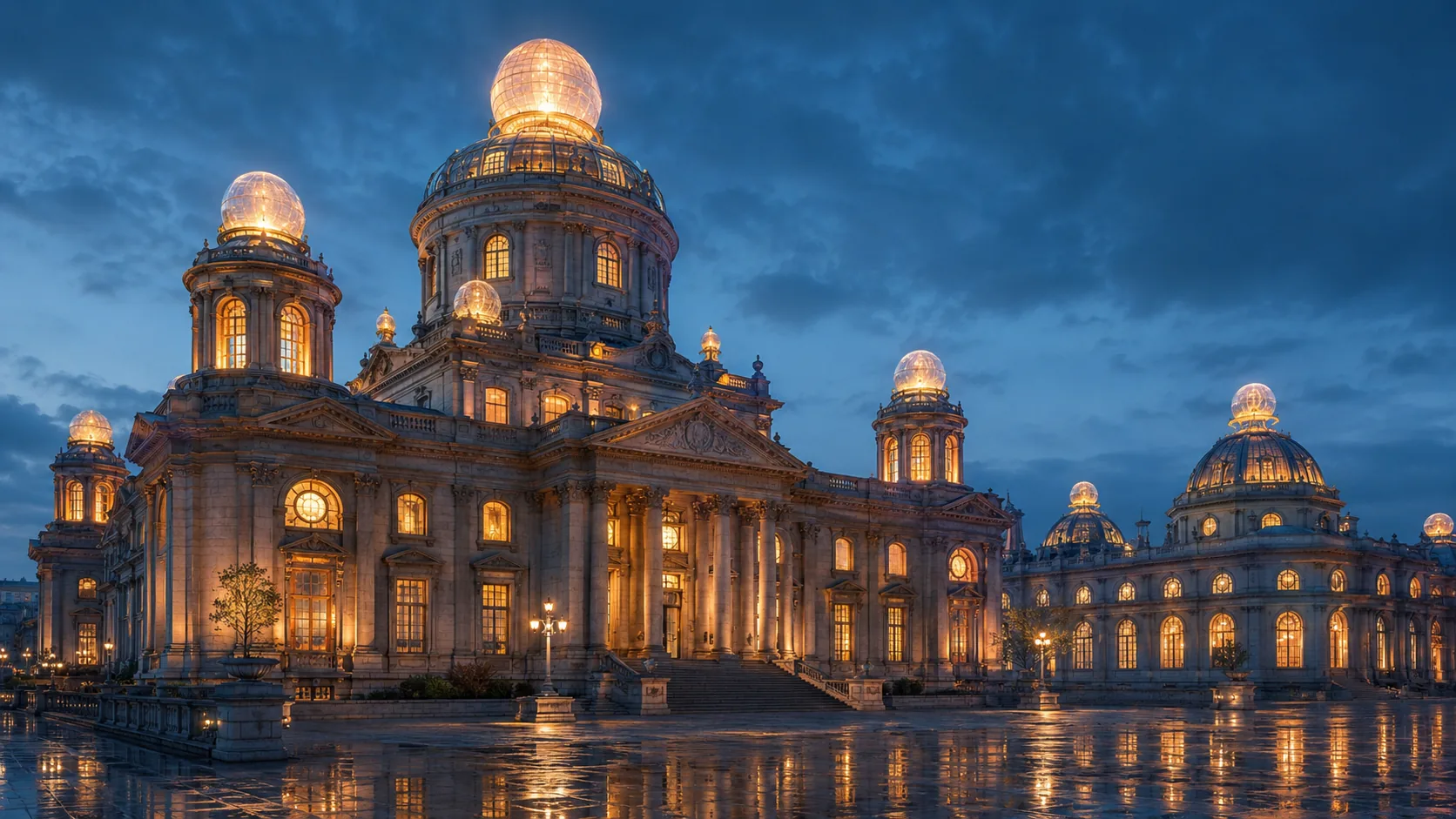
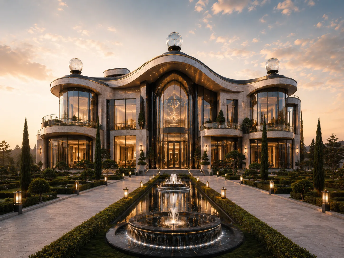
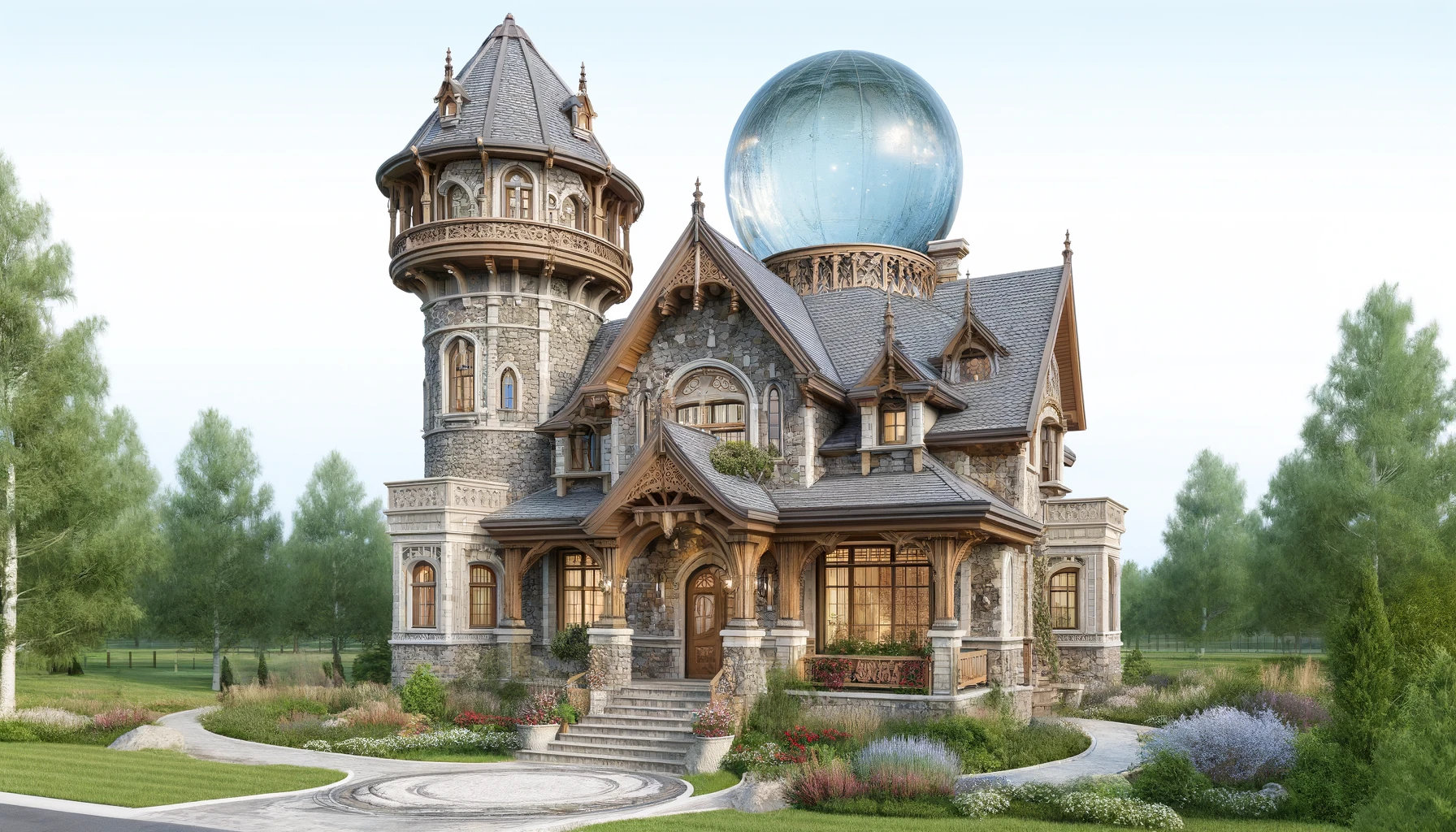
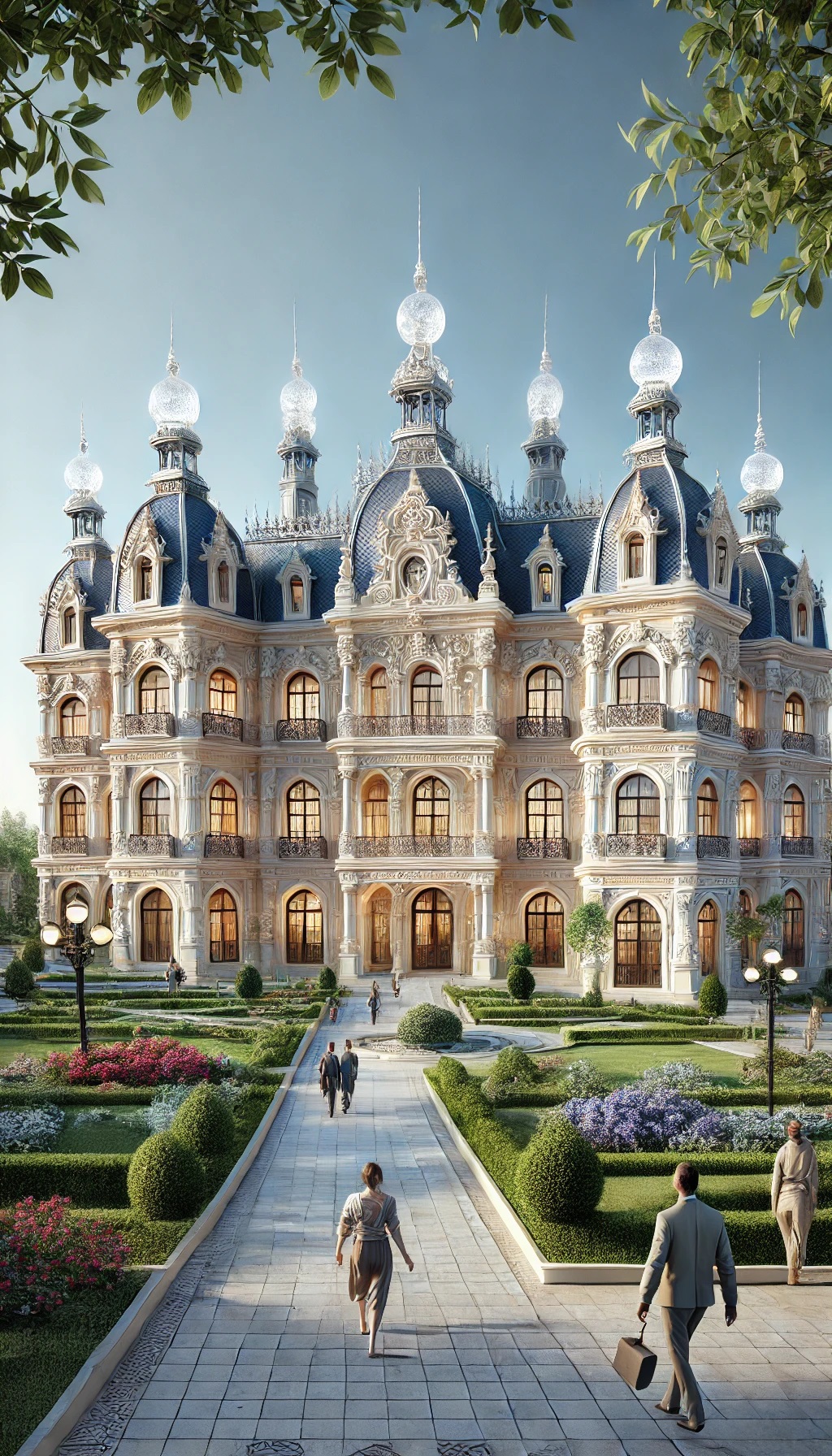
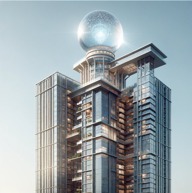
the engines that power their cities. Crystal spheres at the peaks; the building as the machine.
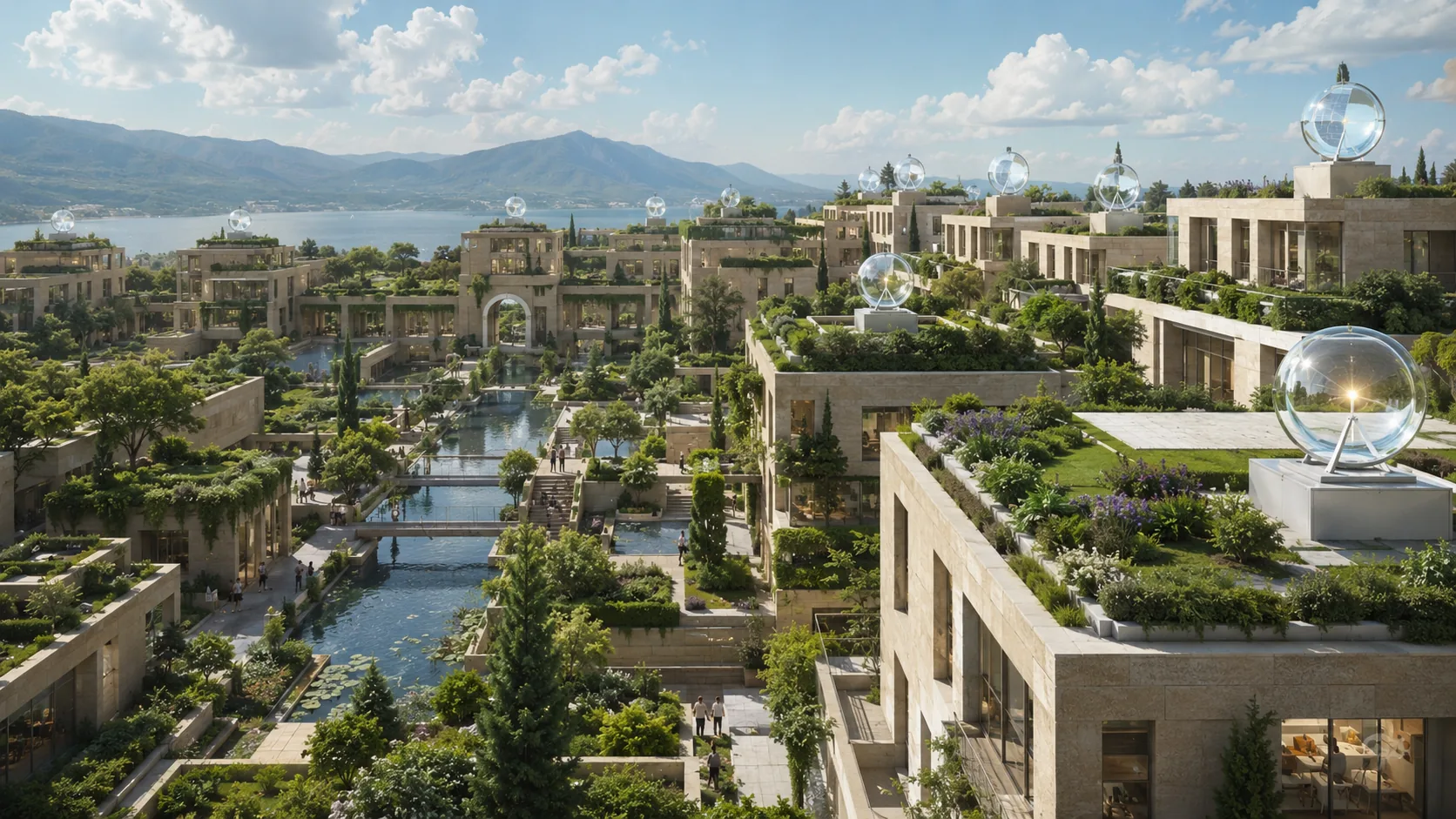
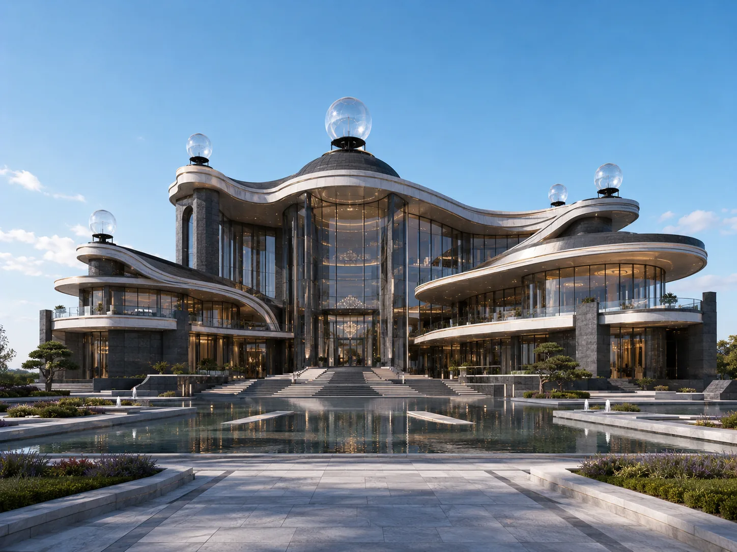
A lens-crowned civic vision (concept)A daylight city built around lightCrystal spheres on every peakThe lens-crowned skylineAn aerial travertine village, roofed in greenA curved glass civic hall under open skyBeaux-Arts stone, crowned with a sphereAn Art-Deco civic hall at golden hourA domed palace glowing at blue hourAn ornate estate catching the last lightThe burning-glass focus, up closeHeritage masonry, reimaginedThe crystal-ball towerSolar-lens architecture studySpherical lens structure
These are the finished pieces. Behind them sit another 140 studies — the sphere
worked out over the roofline again and again, the stone that has to carry it, and the craft
that raised buildings like these the first time.
It was built. It worked. It was forgotten for cheap oil. The physics never changed —
only the price of the alternative did. The future city isn't an invention. It's a reconnection.